Lunos Ventilation Fan - ESPHome

Ventilation fans are pretty common in newer buildings, at least in Germany.
We have E2 series ventilation fans from Lunos installed in our house and I wanted to get them integrated into HA. The only published way I was able to find is emulating the switch usually connected to the 5UNI/FT fan controller. However, looking into the data sheets, all Lunos fan controller, including the 5UNI/FT, can be controlled using an analog 0-10V signal. This has the advantage of having 8 speed settings available instead of 4 and being able to activate the summer ventilation setting (deactivating heat recovery).

After some trial and error, I am now using an I2C 0-10V DAC and an ESP8266 running ESPHome to control my fans in HA. Within ESPHome, I am using the SpeedFan component and two custom outputs. One custom float output for the speed state of the fans and one binary output for the oscillation state of the fans (heat recovery or no heat recovery).

Using the SpeedFan component and the two custom outputs probably is not the most elegant way to implement this, but it works :slight_smile:

Notes:
Initially I was using different PWM to 0-10V modules bought from Amazon and Aliexpress to generate the 0-10V signal, but found them to be unreliable and a pain to calibrate, since their output voltages are highly dependent on the stability of the input voltage. Since the actual input voltage can change quite significantly, depending on the load of the fans and cable length if using the 12V fan voltage to power the PWM module, I switched to the I2C DAC from DFRobot which is much more stable.

The two files below are needed if you want to copy what I did.

Custom ESPHome outputs (CustomLunosOutput10V.h):

#include "esphome.h"
using namespace esphome;
#include "DFRobot_GP8403.h"
DFRobot_GP8403 dac(&Wire,0x58);

// Custom float output for exposing Lunos float state via DAC, taking the binary oscillation state (CustomBinaryLunosFanOutput) into account
class CustomFloatLunosFanOutput : public Component, public FloatOutput {
 public:
  void setup() override {
  // set the DAC output range as 0-10V
  dac.setDACOutRange(dac.eOutputRange10V);
  }

  void write_state(float state) override {
    int DAC0 = 0;
    // fans not active and/or summer ventilation not active (heat recovery active)
    if (id(lunos_oscillating_bool) == true || state == 0) {
      // Convert state to DAC0 output in mV
      DAC0 = (4000 * state + 750);
    }
    // active summer ventilation (no heat recovery)
    else {
      // Convert state to DAC0 output in mV
      DAC0 = (4000 * state + 5750);
    }
    // set DAC0 and save value to chip
    dac.setDACOutVoltage(DAC0,0);
    // write state to global variable lunos_state_float
    id(lunos_state_float) = state;
  }
};

// Custom binary output for exposing Lunos binary oscillation state
class CustomBinaryLunosFanOutput : public Component, public BinaryOutput {
 public:
  void setup() override {
  }

  void write_state(bool oscillating) override {
    // write current oscillation state to global variable lunos_oscillating_bool
    id(lunos_oscillating_bool) = oscillating;
    int DAC0 = 0;
    // fans not active and/or summer ventilation not active (heat recovery active)
    if (id(lunos_oscillating_bool) == true || id(lunos_state_float) == 0) {
      // Convert state to DAC0 output in mV
      DAC0 = (4000 * id(lunos_state_float) + 750);
    }
    // active summer ventilation (no heat recovery)
    else {
      // Convert state to DAC0 output in mV
      DAC0 = (4000 * id(lunos_state_float) + 5750);
    }
    // set DAC0 and save value to chip
    dac.setDACOutVoltage(DAC0,0);
  }
};

ESPHome .yaml file

esphome:
  name: lunos-dac
  libraries:
    - "Wire"
    - "DFRobot_GP8403"
  includes:
    - CustomLunosOutput10V.h

!!!!!...Enter further ESPHome config here..!!!!!

i2c:
  sda: 4
  scl: 5
  scan: false
  id: i2c_bus

globals:
- id: lunos_oscillating_bool
  type: bool
  restore_value: no
  initial_value: 'true'
  
- id: lunos_state_float
  type: float
  restore_value: no
  initial_value: '0.25'

output:
- platform: custom
  type: float
  lambda: |-
    auto custom_float_lunos_fan_output = new CustomFloatLunosFanOutput();
    App.register_component(custom_float_lunos_fan_output);
    return {custom_float_lunos_fan_output};

  outputs:
    id: lunos_dac_float

- platform: custom
  type: binary
  lambda: |-
    auto custom_binary_lunos_fan_output = new CustomBinaryLunosFanOutput();
    App.register_component(custom_binary_lunos_fan_output);
    return {custom_binary_lunos_fan_output};

  outputs:
    id: lunos_oscillation_binary

fan:
  - platform: speed
    output: lunos_dac_float
    name: "Lunos"
    speed_count: 8
    oscillation_output: lunos_oscillation_binary
    
    
2 Likes

Thanks for this solution. Are you using the 5 UNI/FT controller? I have the SC-FT at home and struggle finding a solution for that particular controller as most (in the US) seem to run the UNI/FT controller as well or only want to control the eGO fans.

via SC-FT/SC-RF you’ll connect a 0-10V controller to the 0-10V input on the smart comfort. The wheel should NOT be in the position that says 0-10V, but rather the correct type of fan you want to control.
Connection should look like the picture in the following post (can only embed 1 picture pr post)

Then we get to programming. You can find the correct input values from the 0-10V controller to smart comfort in the picture below. As you can see the values are close to each other so I recommend measuring the voltage on the output from the 0-10V controller as there can be 0,1-0,2V (maybe even more) difference between input and output.
100% =10V, 50%=5V and so forth.

The values on the left side are with heat recovery while the right side are without heat recovery.

NB; you need to program the 0-10V controller with set values, non-dimmable.

I’ve wired up to an ESP01 (IO0 and IO2) and used the config above (with pins 4,5 specified), compiled and uploaded.

On the serial port, it does look like it’s booting fine and contacting my HA just fine.

[C][i2c.arduino:053]: I2C Bus:
[C][i2c.arduino:054]:   SDA Pin: GPIO4
[C][i2c.arduino:055]:   SCL Pin: GPIO5
[C][i2c.arduino:056]:   Frequency: 50000 Hz
[C][i2c.arduino:059]:   Recovery: bus successfully recovered
[C][speed.fan:016]: Speed Fan 'Lunos'
[C][speed.fan:151]:   Speed: YES
[C][speed.fan:152]:   Speed count: 8
[C][speed.fan:155]:   Oscillation: YES
[C][mdns:108]: mDNS:
[C][mdns:109]:   Hostname: lunos-dac
[C][api:138]: API Server:
[C][api:139]:   Address: lunos-dac.local:6053
[C][api:143]:   Using noise encryption: NO
[D][api:102]: Accepted 192.168.34.118
[D][api.connection:961]: Home Assistant 2024.3.0 (192.168.34.118): Connected successfully
[D][fan:021]: 'Lunos' - Setting:
[D][fan:030]:   Speed: 8
[D][fan:092]: 'Lunos' - Sending state:
[D][fan:093]:   State: ON
[D][fan:095]:   Speed: 8
[D][fan:098]:   Oscillating: NO
[D][fan:021]: 'Lunos' - Setting:
[D][fan:024]:   State: OFF
[D][fan:092]: 'Lunos' - Sending state:
[D][fan:093]:   State: OFF
[D][fan:095]:   Speed: 8
[D][fan:098]:   Oscillating: NO

[D][fan:024]:   State: ON

In my HA, I have a single control:

Screenshot 2024-09-03 at 1.09.19 PM

and I can turn the fan on/off as also shown in the log above. I was expecting to also see a control to adjust the speed but maybe I have to add the Custom controls into my config manually?

Also, regardless of what I do, I never actually see any I2C transactions on either the SDA or SCL pins (using my oscilloscope). I’ve tried 4, 5, 0, 2, GPIO4, GPIO5, GPIO0, GPIO2, etc. I’m pretty sure 4,5 are what should work.

No voltage coming out the DFRobot board either.

Thoughts, anyone?

Here’s my yaml:

esphome:
  name: lunos-dac
  platform: ESP8266
  board: esp01
  libraries:
    - "Wire"
    - "DFRobot_GP8403"
  includes:
    - CustomLunosOutput10V.h

wifi:
  ssid: "xxx"
  password: "xxx"

logger:

api:

i2c:
  sda: 4
  scl: 5
  scan: false
  id: i2c_bus

globals:
- id: lunos_oscillating_bool
  type: bool
  restore_value: no
  initial_value: 'true'

- id: lunos_state_float
  type: float
  restore_value: no
  initial_value: '0.25'

output:
- platform: custom
  type: float
  lambda: |-
    auto custom_float_lunos_fan_output = new CustomFloatLunosFanOutput();
    App.register_component(custom_float_lunos_fan_output);
    return {custom_float_lunos_fan_output};

  outputs:
    id: lunos_dac_float

- platform: custom
  type: binary
  lambda: |-
    auto custom_binary_lunos_fan_output = new CustomBinaryLunosFanOutput();
    App.register_component(custom_binary_lunos_fan_output);
    return {custom_binary_lunos_fan_output};

  outputs:
    id: lunos_oscillation_binary

fan:
  - platform: speed
    output: lunos_dac_float
    name: "Lunos"
    speed_count: 8
    oscillation_output: lunos_oscillation_binary

Update to my prior post. Looks like I must have just pooched the 2 GPIOs on my ESP01. I swapped it out and wired up an ESP07 I had lying around and now I’m getting I2C and the DAC is switching from 0 to 4.9v which I guess is expected. Also, my DFRobot board was shipping with A0/A1/A2 set to ā€˜on’ so the I2C address was 0x5f instead of 0x58. Setting all switches off solved that.

@haavhaal I’ve got my esphome+dfrobot DAC successfully applying voltage in the 6-10v range and my rocker switches disconnected. I would expect that the fans would run at variable speeds with no oscillation. I’ve measured the voltage at the TAC pins on my 5/uni-ft and even at lower voltage like 6.9v, the fans spin at full speed and reverse direction approximately every minute. From the chart above, I am of the impression that they should spin slowly and not reverse direction frequently? In fact, the fans don’t change speed regardless of the voltage on the TAC pins.

I have my DAC wired to GND and 0-10v pins on the ā€œTAC connectorā€. The +12v pin on the TAC connector is not connected; I assume the +12v pin is an output.

Dial switch set to ā€˜3’.

Screenshot 2024-09-15 at 8.53.05 AM

@haavhaal I’m interested if you know anything about the digital T/R pins on the Lunos contrrol board, or the 6-pin connector that it uses to connect to things like the Gesture Control module?

The 0-10V input is a good option, but really only provides control over the speed of the fan and how often they swap direction (in essence, whether heat recovery is in effect or not).

I’d like a little more control, specifically to manage the speed and direction of each fan independently. I have a few use cases for this, including:

  1. Experimenting with adjusting the cycle time of fan reversal based on interior and exterior temperatures to optimize for the heat core saturation;
  2. Switching both fans to exhaust mode in the event of a fire (to create a negative pressure in the building and hence help suppress the fire).

I’ve not been able to find any documentation on the Lunos website, but thought I’d ask before I start trying to reverse engineer a serial protocol.

Hi

Response time is ridiculous (I realize I need to turn on some kind of notification…), but thought I could comment anyway.
There’s two ways you to maybe be able to do this, but it would I’m not certain it will work.

  1. Diagnose software (if you have or get a TAC)- Diagnostic software - LUNOS

  2. Provide voltage directly to the fans without going via the smart comfort. there are a million possible pitfalls, but if you have a reliable and very carefully calibrated voltage reader and a very very correctly calibrated power supply it is doable.

For the second options I would recommend that you first connect 0-10V to the input of the smart comfort and then measure the output to the fans. that way you could record the voltage values for the different stages, but also the timing and speed and more of the curve of the voltage supply. next you have to write some kind of programme that makes it possible to fine tune these values and timing ā€œliveā€ while a fan is connected.

these are the 0-10V input values. they are NOT the same as the output voltage to the fans.

I don’t recognise that version of the universal control. could you send me the version nr, please?
I’m not an expert on TAC, unfortunately. But a tip is to download the german version of the manual. it’s a lot more detailed.

sorry, I just noticed you were talking about DAC.
as long as the 0-10V signal voltage from your transmitter is connected to + (positive) and the - (negative) from the 0-10V signal transmitter is connected to - (negative), the values in the picture above should be correct.

Thanks.

Since my post above, I had contacted Lunos Canada with the problem and they told me the dial switch had to be set to ā€˜E’ to use the 0-10v. However, when I do that the fans just come on full regardless of the DAC or W1/W2 switch settings. After that they stopped responding to email. I think they’re wrong so I ignored them.

I can’t find the unit I have on the website. However, I feel like the website has changed a lot since I first received my units. Here’s a link to a photo album of my controller and wiring to my DAC. Also a couple shots of my meter as I’ve set the output voltage to various settings. Regardless of output voltage, and with W1/W2 open, the fans just spin up to full speed and oscillate in their usual manner. There’s no speed change that I can hear regardless of voltage

Hei

The dial should not be set to ā€œEā€! If it is then the controller will send 0-10V signal on the output to the fans.
Dial should always be set to the kind of product that’s connected to the output on the controller.
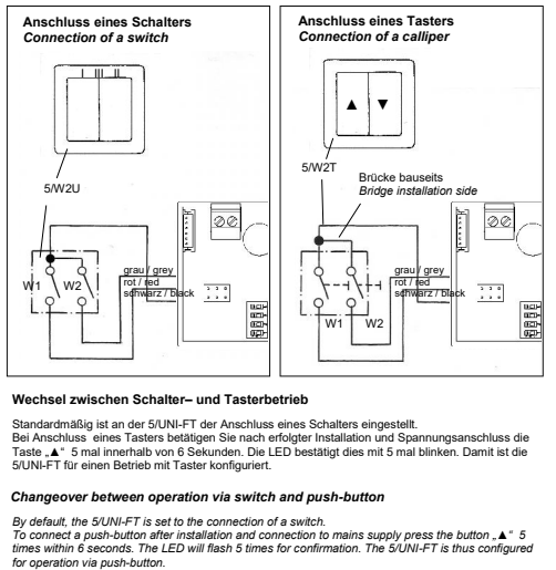
I think a part of your problem is that there’s a conflict between the two different input signals. If you have a 2ch relay set as a switch (OFF/OFF, ON/OFF, OFF/ON, ON/ON) it will create conflicts.
The solution is to change how the controller perceives the input from the relay. You need to change from switch to push (see picture).

That should do the trick. Let me know how it goes.
Good luck

Thanks for that. I think lunoscanada needs some training; but… moving on.

So I tried it. I toggled my W1 pushbutton 5 times, ending with W1 off (and W2 off still). I saw the LED flash 5 times. After that, I couldn’t make the fans do anything. Treating the switches as push buttons, turning W1 on-off or W2 on-off or W1+W2 on-off (maybe 100ms ontime), the fans wouldn’t spin. Also no life from using the 0-10v input. I measured the voltage going into gnd and 0-10v input and it’s correct according to the chart above. But the fans don’t spin.

Believing that maybe I’d killed the units, I toggled W1 5x again and saw the LED flash 3x and then the fans came on full/oscillating. I was then able to switch W1/W2 and make the fans behave as they had before.

So I think I’m confused. When in pushbutton mode, I’m sure I didn’t flip the switches so fast as to create long bounces. I did try varying the on-time just in case I was faster than the debounce algorithm. I even tried leaving the switches on for several seconds. Nothing.

I feel like there’s something I’m not understanding. Regardless, I expect the 0-10v to do something, even if I wasn’t using the ā€˜pushbuttons’ correctly.

Thanks for explaining. I realize that my former post was lacking a couple of important points.
First, could you send me the setup/settings of your relay, all parameters you can find.
Second, the push button should have a small spring inside so the button will automatically return to its normal state.
Third, can you measure the output voltage to the fans (S1 and minus and the S2 and minus) on a couple of different speeds?

is your input voltage under or over 5V?

If we can’t make this work but you still want a physical button there’s a way to make that work. disconnect it from Lunos and connect it to a dry contact relay (voltage-free). then config it to increase 0.5V on one button and decrease by 0.5V on the other. that’s the difference between each step in the 0-10V input. you need to make a logic that makes sure you don’t use the values between 4.9V and 6.1V and not below 0.6V too.

I might also not being clear. My current setup is the controller is outside of the office that the fans are in. There’s a switchplate on the wall of the office just has two regular residential light switches wired up to W1/W2. The controller is in a box mounted on the wall and is mated to an ESP32 with a DAC. The DAC output is connected to the controller’s gnd/0-10v input. My dial switch is currently set to ā€˜3’.

So currently the wall plate switches don’t have a spring so I’m pretending they’re a pushbutton by toggling them, for the purposes of conducting your experiments. If it turns out I need to change them to pushbuttons in the future, I can do that.

My goal is for HomeAssistant to control the fans most especially in the summer so I can disable oscillation and get some summer free cooling. In the winter, I want to control the humidity to some extent by enabling/disabling the Lunos fans via HomeAssistant automation.

I will measure the S1/S2 voltage later today and post back.

The input voltage (at 0-10v) that I was measuring yesterday was over 5v.

I actually don’t need the buttons on W1/W2 if I can get HomeAssistant to control the fans independently. The buttons are there now because I couldn’t get that working and so my wife can control the Lunos manually.

I see.
my suggestion is that you disconnect Lunos from the switches and just use 0-10V. if you want to be able to control the ventilation manually with buttons I would recommend using a wireless switch with for example 4 buttons. configure those to trigger certain 0-10V input voltages. then you will be able to change levels easily. remember to set them as mutually exclusive

Thanks.

I disconnected the W1/W2 buttons yesterday and applied voltage on 0-10v, as measured with my meter but still no behavior on the fans. I can’t get my probes into the S1/S2 pins without disconnecting the fans (but now that the weather has warmed up, I’ll strip more insulation off the wires so I can get my probes onto them.

you don’t have to have the fans connected. the ouput on S1 and S2 will be the same regardless.
I find it very strange that the fans don’t react to 0-10V input. you can send me a pm with your set-up and parameters if you like. or post it here. up to you :slight_smile:

Can someone help figuring out why preset mode ā€œsummerā€ does not work for me? I get a message that says ā€œFailed to perform the action fan/set_preset_mode. name ā€˜PRESET_SUMMER_VENT’ is not definedā€. I have installed three Lunos e2 60 fans with 5/UNI-FT controller and hooked it up with two relays to adjust fan speeds from Home Assistant.

Hi

Summer vent is trigger by a toggle of the correct relay channel. I would be ch2 or the right button if you control the UNI via a double wall switch (shown i the manual).
Summer vent runs for a maximum of 8 hours. After that you can toggle again to reactivate it. If you toggle before the UNI has returned to heat recovery mode it will deactivate summer vent.
Hope that was close to understandable…

Apparently I’ve had notifications turned off, hence my lack of response in here.

I’ve read through the thread. A couple of answers to questions asked along the way:

All controllers, UNI-FT and SC-FT, can be controlled by 0-10V. There are a couple of hardware revisions for both the SC-FT and UNI-FT controllers differing in layout. I am guessing that the firmware on the newer version is identical between UNI-FT and SC-FT because I can use the SC-FT button piece with a UNI-FT controller with no issues. For the approach mentioned in the first post I am currently using a newer UNI-FT without any switches attached. The dial needs to be set to the correct fan type, not! to E (0-10V). Depending on the fan type summer ventilation mode is available or not.

Sine my initial implementation ESPHome has removed the custom component feature and recommends to use an external component instead. I’ve haven’t had the time to port yet.

If someone owns an SC-FT and wants to play around with it, the button piece communicates with the controller via UART. I wasn’t able to make complete sense of it. Maybe someone else can. This would be another possible way to implement controlling the fans.

Since the fans themselves are controlled via 0-10V, another way is to ditch the Lunos controller entirely and directly control the fans via the two available DAC channel.

Your summary is quite correct.
Regard possible alternative ways of controlling Lunos;

The button piece of the SC-FT doesn’t do much tbh. If you use the voltage-values as input on a SC-FT it will indicate the corresponding commands. if you set values for stage 1 (1,1 V - 1,4 V) it will light up the 1st led (from left to right) and so forth. if you set values over 5 V it will light up the corresponding led and the ā€œsunā€, indicating summer mode.
the function of the other buttons are easily replicated with some logic (boost mode, reduced level at night, filter cleaning reminder).
the button piece does have a humidity sensor and it’s possible to control the ventilation with that. but it’s not often the SC-FT is installed in a relevant positions, so I recommend using an external sensor, IF you choose to use relative humidity as the controlling input. I do not recommend doing that as it will then shut you out, only letting you change levels for an hour before taking control again.
so, in short; the button piece has no relevant function that can’t be replicated in HA.

regarding ditching the Lunos controller entirely;
it is possible and I’ll even give you the correct voltage output for the different steps in both exhaust and supply mode.
however, what you can’t (or at least I can’t) simulate is the logic that decides how it changes direction, ramp-up and ramp-down (if that translates well enough to english). that is basically the main purpose of the controller, in order to maximize heat recovery and minimize the sound/noise impact.

hope that was somewhat informative, fingers crossed
:slight_smile: