I have a pressure mat that has 4 cables (all black) but I only use 2 of the 4 and they are just attached to an aqara leak sensor set in occupancy mode which works pretty much flawless since setting it up.
You just need to see what 2 of the 4 will allow a closed circuit when pressure is applied.
Still struggling with this one. I’ve got the four wires each hooked up to a GPIO on an ESP32 and the voltage readings don’t really give me any indication when someone’s in bed (see graph below).
Green/Yellow have continuity as do Black/Red. I’ve tried connecting G/B, G/R, Y/B, and Y/R and don’t get any significant readings across them with a multimeter when there’s someone in bed.
You’re not supposed to be connecting those wires directly to GPIO. What you’re supposed to be making is a resistor network that allows you to sense voltage differences in the range of 0–3.3V and therefore measure the change in resistance.
Hang on…
Find the two leads that have some sort of resistance that varies with weight using your multimeter (it should be high normally and drop down when squeezed hard).
Then use those two leads as part of our resistor network, with a decent amount of resistance added in the network (in my case I used 460k ohm IIRC). I will share below my own sensor’s schematic.
Then you will have a sensor that will get you a variable resistance or variable voltage. When the resistance goes below a certain setpoint, that means detection.
On top of that you can add debouncing using the delay on and delay off ESPhome constructs.
Thank you so much for that detailed reply. I finally had time to dig in to this and replicate your circuit (I think) and I’m not getting the results you describe.
I’ve tried with every permutation of the orange and brown wires with the R/B/G/Y wires from the sensor pad, but I think the yellow and green are the correct pair.
Regardless, the logs show the same values over and over, even with pressure on the sensor:
[12:10:04][D][sensor:093]: 'GPIO5': Sending state 3.10700 V with 5 decimals of accuracy
[12:10:04][D][resistance:039]: 'Variable resistance 1' - Resistance 33733.5Ω
[12:10:04][D][sensor:093]: 'Variable resistance 1': Sending state 33733.47656 Ω with 1 decimals of accuracy
[12:10:06][D][sensor:093]: 'GPIO5': Sending state 3.10700 V with 5 decimals of accuracy
[12:10:06][D][resistance:039]: 'Variable resistance 1' - Resistance 33733.5Ω
[12:10:07][D][sensor:093]: 'Variable resistance 1': Sending state 33733.47656 Ω with 1 decimals of accuracy
[12:10:09][D][sensor:093]: 'GPIO5': Sending state 3.10700 V with 5 decimals of accuracy
[12:10:09][D][resistance:039]: 'Variable resistance 1' - Resistance 33733.5Ω
[12:10:09][D][sensor:093]: 'Variable resistance 1': Sending state 33733.47656 Ω with 1 decimals of accuracy
[12:10:11][D][sensor:093]: 'GPIO5': Sending state 3.10700 V with 5 decimals of accuracy
[12:10:11][D][resistance:039]: 'Variable resistance 1' - Resistance 33733.5Ω
[12:10:11][D][sensor:093]: 'Variable resistance 1': Sending state 33733.47656 Ω with 1 decimals of accuracy
GPIO35 (or equivalent pin chosen in the ADC sensor of your YAML)
460K resistance
Other side of 460K resistance to GND.
Skip the capacitors for now.
You should see the ADC value change up or down when you compress the resistance. It’ll be noisy because of no capacitors, but at least you can confirm it’s happening and you can add the caps later.
Also, what is the range of resistances your thing goes over? You may have to select a different resistance to get a good ADC measurement.
Unfortunately, nothing changes. During the esphome logs output below, I was applying various levels of pressure to the pad, up to and including my full body weight. Nothing changed.
[09:38:10][D][sensor:093]: 'GPIO5': Sending state 3.10700 V with 5 decimals of accuracy
[09:38:10][D][resistance:039]: 'Variable resistance 1' - Resistance 33733.5Ω
[09:38:10][D][sensor:093]: 'Variable resistance 1': Sending state 33733.47656 Ω with 1 decimals of accuracy
[09:38:12][D][sensor:093]: 'GPIO5': Sending state 3.10700 V with 5 decimals of accuracy
[09:38:12][D][resistance:039]: 'Variable resistance 1' - Resistance 33733.5Ω
[09:38:12][D][sensor:093]: 'Variable resistance 1': Sending state 33733.47656 Ω with 1 decimals of accuracy
[09:38:15][D][sensor:093]: 'GPIO5': Sending state 3.10700 V with 5 decimals of accuracy
[09:38:15][D][resistance:039]: 'Variable resistance 1' - Resistance 33733.5Ω
[09:38:15][D][sensor:093]: 'Variable resistance 1': Sending state 33733.47656 Ω with 1 decimals of accuracy
[09:38:17][D][sensor:093]: 'GPIO5': Sending state 3.10700 V with 5 decimals of accuracy
[09:38:17][D][resistance:039]: 'Variable resistance 1' - Resistance 33733.5Ω
[09:38:17][D][sensor:093]: 'Variable resistance 1': Sending state 33733.47656 Ω with 1 decimals of accuracy
[09:38:20][D][sensor:093]: 'GPIO5': Sending state 3.10700 V with 5 decimals of accuracy
[09:38:20][D][resistance:039]: 'Variable resistance 1' - Resistance 33733.5Ω
[09:38:20][D][sensor:093]: 'Variable resistance 1': Sending state 33733.47656 Ω with 1 decimals of accuracy
[09:38:22][D][sensor:093]: 'GPIO5': Sending state 3.10700 V with 5 decimals of accuracy
[09:38:22][D][resistance:039]: 'Variable resistance 1' - Resistance 33733.5Ω
[09:38:22][D][sensor:093]: 'Variable resistance 1': Sending state 33733.47656 Ω with 1 decimals of accuracy
When I hook the pad to the meter directly, it hovers around 1.2-1.3Ω unloaded. Adding weight causes it to drop to 0.8-0.9Ω, and as I remove the weight it goes up to anywhere from 3-4Ω. Over the next 30 seconds or so, it slowly settles back to around 1.2Ω.
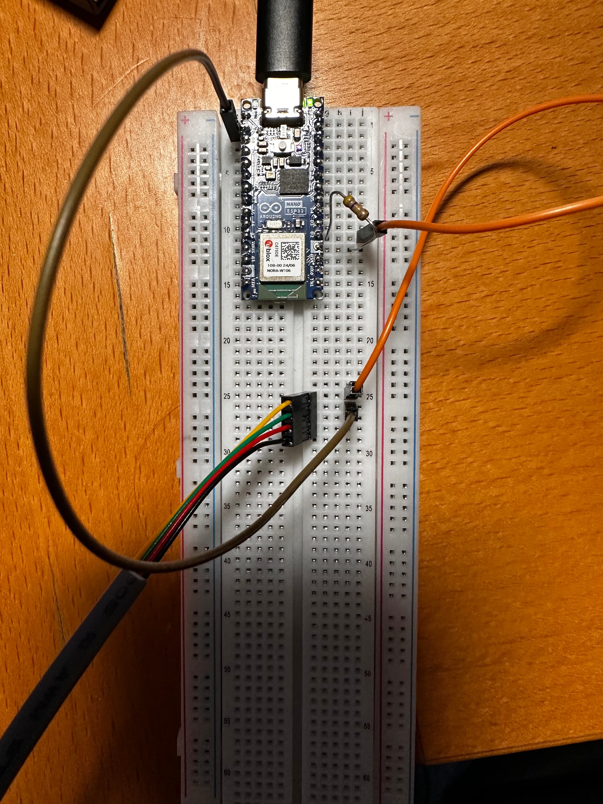
Updated circuit photo just for verification/sanity check:
Oh my god, 0.8 ohms??? I am at a loss of how to measure that with a voltage divider network without frying the ESP’s pads. For all i know they might already be fried! If you connected it to the ESP, that would have caused 3.3+ amps or more to flow thru the pad, rated max for 0.02 amps.
Ok, then I’m just going to wait until the guy manufacturing the dual bed sensor gets some more made. I truly appreciate your time and guidance, @Rudd-O!
I was also trying to set up bed sensors. After getting some in the mail, I found out they’re the same thing as home Dance Mats. I bought some myself, wired them up, and found they were unreliable; sometimes working, sometimes getting stuck “pressed”. Might’ve just been the ones I bought, but each one was $43 USD! Those also had 4 wires, but I was only using 2.
I’ve been spending time trying to figure out if I missed anything and came across this thread (as well as many others). It’s possible I needed something more complex.
Using a large Capacitor instead
Because you guys were talking about measuring the resistance, I wanted to point out this guide I used:
It talks about using two pieces of aluminum foil on either side of a sheet of paper. You’re measuring capacitance without a special circuit. In my testing under couch cushions, it totally works! Haven’t tested with the bed just yet. Calibration is also very simple. Hardest part was filtering down results such that it wouldn’t go On-Off-On-Off-On a billion times.
I really thought it was a fake article because of how stupid it sounded: no fluff; no crazy circuit. You can do the whole thing in software, but you do need at least an ESP32 which has capacitance monitoring circuitry.