Hi,
I am new to HA.
I am planning to hook up a MCP23017 to my HA system
Found some integration documents to setup the I/O pins, there is no info to adjust the config register when the chip boots up to allow build in functions. I want to enable the interupt output as soon as a input pin on the MCP changes state. Int A for A port and INt B for B ports
I wrote the MCP23017 component for HA, I didn’t originally add the interrupt functionality because the library that I used to developed it was missing some needed functions (Adafruit_CircuitPython_MCP230xx), I implemented those functions into that library later on through a PR (Improve interrupt) and then added some interrupt functionality into a repository in my github account for testing purposes with the idea of adding such functionality into the HA component. Well, that proved to be more difficult than expected since it presents some odd behavior at times, here is the link to my custom_component repository in case you want to give it a try. At the moment it is hard coded to have a mirrored open drain interrupt for both A and B ports on any change state, you can see these in the binary_sensor.py file lines 102-103.
StephenBeirlaen on github helped improve the interrupts to work with multiple MCPs chained to one interrupt pin in the Raspberry Pi, but we had some reliability issues using the INTFLAG, we haven’t been able to find out what the issue is and I haven’t had the time to really look into it. Life gets in the way some times, so if you can help improve this component that would be awesome.
Any way, if you need any help let me know. I will try to be better at responding to these posts.
I finally managed to get the circuit board done. I am setting up your custom_component.
I was wondering how does the pins: work.
Does it follow the AdaFruit setup?
|Physial Pin #|Pin Name|Pin ID|
|21|GPA0|0|
The installation is a bit different on my Pi4B with the latest HA i have to use the community SSH & Webterminal to get in and send over the files. the homeassistent user is not there and it seems that the path is right under config where i have to create a folder named custom_components and place this one in. Not sure if i will work, will find out soon.
I got it figured out, found some more posts that made the puzzle complete.
I am now making modifications to my board, i didnt get a 0 - 5v level on the inputs
MCP23017 - ULN2003A (i missed the bias resistor with the internal pulldowns).
besides that it shows up in HA now, i will make a pull request with all i found to makeit work.
I’m doing something similar to you if I’m reading correctly, and having issues getting the MCP23017 to work properly with HA on a Pi4B.
I’m trying to use an MCP23017 for 8 binary_sensor inputs and 8 switch outputs driving a ULN2803A which in turn drive 8 12V relays to control lights.
So far I’ve got the MCP23017 showing up in HA with no errors and the switch outputs work, albeit a little unreliably so far, but the binary_sensor inputs don’t work at all.
From what I’ve read online, pulling an input to ground on the MCP23017 should trigger the binary_sensor but it’s not doing anything.
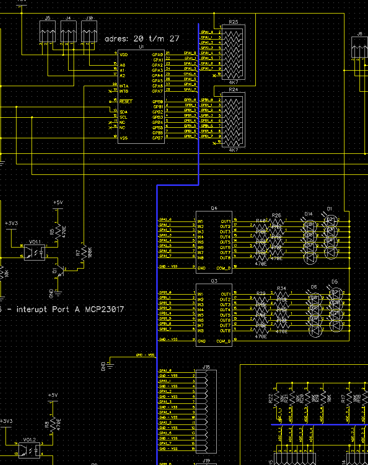
I’ve attached my schematic if that helps?
Any assistance you can give would really be appreciated.
I have the binary_sensors up and running, when i do a HA restart all states are read corectly. without the restart the pin are not updates as i expect.
After some debugging by modifing the script to display some more data and reverse engineer the working of the HA integration ( as i didnot quite understand the documentation) i found that the binary_sensors are read correctly when HA restarts.
I use 2 chips, the issue i now have is that one chip is setup correct, so all registers are written as i expect:
pitn to output, interupt mode to mirror and active_high and on any change.
One chip was written as i expect, the other has just input pins. When i change a pin it triggers an interupt and that reads all states, the states are reflected in HA. only one chip reports the state back, so triggering a pin on the onter chip doesnot do a thing in HA as the new level is not retrieved.
I have modified the code to reflect my changes and added some debug commands when the integration logging is set to debug. I think that my printboard (that i wired manualy) has a wrong i2c bus setup. I will make some modifications to the layout and add some condensators an the powerlines as close as pisoble to the individual ic’s to rule the i2c bus out.
From the code it seems that it should work and with the restart of HA is sort of shows it will read the states. I have a Pi3B laying here to wait for conversion into Mysensors gateway, i might use that to see if the HA on a Pi3B works as expected. HEre is a sniped of my chematic, i can upload the full one f you would like to have a look. I use external pull-ups and pull the pin low with a reed contact. When i goes up i detect this. I use a ULN to drive a LED to reflect the state. The resistor values in the schematic are wrong as i miscalculated this (i need to update the schematic to reflect the good settings). One thing i learned you have to be above 0.8xVDD (that would mean 4.0V at a 5V powersupply, or in my case 4.1V with 5.2V comming from the Pi4) to have a 1 on the port, so if you are below that and pull it low, it was already low.
Once i made the electrical changes i wil test agian and adjust the python code if needed. I will update the results and provide the updates to Jardi so he can update the repo.
Kind regards,
Peter
I am using MCP23017 for several months with no issue.
Using “standard” integration included with HA, which unfortunately does not use interrupts so my inputs are read once every second. This is so far OK as the input I have on it are not time critical.
However I am planing some changes and fast reaction for input will be more needed. Also with interrupt sensed by RPi it logically is more “economic” design.
1: The int routine is unstable. more details are on the repo. I am also looking into the working of the code vs why the int does not work as stable as one would expect
2: Create the component in the custom_component folder use the config as documented and you are ready to go.
Thank you @Peerke
2: I have created subfolder for MCP23017 integration: \custom_components\mcp23017 and placed files from github repo.
Unfortunately I have the following error in log:
Invalid config for [binary_sensor.mcp23017]: [interrupt_port] is an invalid option for [binary_sensor.mcp23017].Check: binary_sensor.mcp23017->interrupt_port.
(See /config/configuration.yaml, line 120).
Please check the docs at https://www.home-assistant.io/integrations/mcp23017
I wonder how HA knows that it should use custom integration rather then “built-in” ? Especially that the name in the configuration.yaml are the same… ?
EDIT:
After reverting configuration.yaml to previous structure (and with custom component installed) my sensor is working fine. And in the detailed log I have the following entry:
2020-10-14 19:38:44 ERROR (SyncWorker_0) [homeassistant.loader] Error parsing manifest.json file at /config/custom_components/mcp23017/manifest.json: Expecting value: line 6 column 1 (char 5)
The in binary_sensors.yaml i have this:
Note that: active_high is not in the original code. My schematic had no support to change to opendrain so i modified the code of binary_sensor.py to sent some the correct value to the register in the MCP chip. after this it loads correctly. I never new there was a default integration of the MCP23017.
pull_mode DOWN also does not exists, there is no pull-down resistor in the IC, you need to put them in yourselves. So same here i modified the code a bit to discard the ‘UP’ and make sure its not pulled_up at all.
Hopes this helps you on your way, it took me hours and hours to figer this one out.
I wonder how your setup runs. I have a PI4 and the mcp23017 registers are not written as expected meaning that the interupt is not configured and therefor does not work.
My guess is that the mcp object within the script is not used correctly messing things up.
I need some time to play with the code and test it out.
Thank you @Peerke !
I have modified manifest.json the same way as you and after that I am able to restart HA with no errors except warning: BinarySensorDevice is deprecated, modify MCP23017BinarySensor to extend BinarySensorEntity - which at this point seem to have no negative effect.
So far my switches seem to work fine and my binary.sensor also works. So this is good starting point. Tomorrow will try to check/measure the response time. But it works without scan_interval: parameter (which is part of default MCP23017 integration).
I have removed interrupt_mode: - probably becasue I did not modify binary_sensor.py
At this point I have pull_mode: DOWN and seems to work fine.
It does help me a lot however what worries me is your statement:
If I can help here let me know. Will do some test tomorrow with measurements of interrupt levels.
Yes, there is (Removed integration - Home Assistant) and I was using it so far with no issues (both sensor and switches). The challenge was when I wanted sensors to react instantly rather then 1-1,5 seconds (reality). This “default” integration does not use interrupts and instead you can set “scan_interval” (min. 1s) - in my view this means that default integration can only be used for switches or sensor which can detect state with few seconds delay.
The error is because the this used methode is depricated, it can be found on line 9 of the binary_sensor.py. I made the change localy and was planning (as soon as the int worked as it should) to push an update with all i had done. For now its working, in the future it might not anymore.
The interupt_mode has an default in the binary_sensor.py, its it set as ‘opendrain’.
also does the pull_mode.
If you can provide soem feedback around your findings that would be great.
MY sensors showed up with the correct state, as soon as i change one HA did not respond. After a lot of googling and trying i found out how to alter the code so i had debug level logs and i added some ectra lines. It looked like the routine did a good setup of the i2c chip with the right registers. At the end of the setup i pulled the config out of the chip (at least i think it works like that when i look at the examples provided by adafruit) and the registers where not set at all.
So either my circuit mailfunctions or the routine doen’t do it’s job.
One other thing i first tried is to have 2 chips installed, and 1 of the 2 had correct registers and worked but not all ports corresponded as i expected. So i decided to remove 1 chip and start testing just with 1. and that is where i ended with the log lines that the registers where not set.
So some strange things are going on that i cant get my head around.
One thing i noticed is that in most examples the mcp object is created and then updated. In the chips setup the mcp object is stored in a dict and then pulled out. in don’t see any action after a change to the object and then be overwritten in the dict. Dont kwon yet if that is good or not. My first plan was to always overwirte the mcp object in teh dict after updates on ports or settings or even remove teh use of the dict and recreate the object every time (just to see what happens then).
Hope your findings are fine, that would mean both my chips are fried or the board has some sort of wierd behaviour.
Good info @Peerke !
I did not have much time today but done a test with disconnected interrupt from MC chip and RPi (using RPi4B and MCP23017) and binary sensor did not work. Connecting to another INT works fine.
This means to me that interrupt is working OK. Next testing will be to check precisely the speed of reaction as observing it for last 2 days it does not look like faster than “default” integration (appr. 1-2 seconds).
I am also planning connecting second chip to RPi and what you write worries me… When I look at config I wonder if the interrupt_port: is in the right “section”. What I mean is that each MCP chip should be connected to separate RPi GPIO ? If not that means that several MCP chips interrupts connected to one RPi input would result in checking all MCP chips binary sensors. Maybe this is the logic. Or maybe not and this might be a problem you have experienced.
Good to know it works as expected. Need to look at the i2c bus why its seems unstable.
The interupt works with opendrain, those can be connected together so the Pi reacts to the same RPI port. The code does a scan on both (or better all) chips and updates the state in HA.
The routine to check the interupt flags in each chip is to buggy and therefore the creator choose this way to do it until a more stable reading can be achieved.
I guess it takes longer time to do a full scan then just read te chip and get the updated port.
If the interupt way takes as long as the default then the need for this complexity is not needed.
I wanted the interupt way for the same reason as you, instant reaction in HA on a pin change.