Hey, so after some time do you still believe the WF-60A1 IR receiver does nothing? Did you end up just aiming your IR transmitter at the wall controller instead?
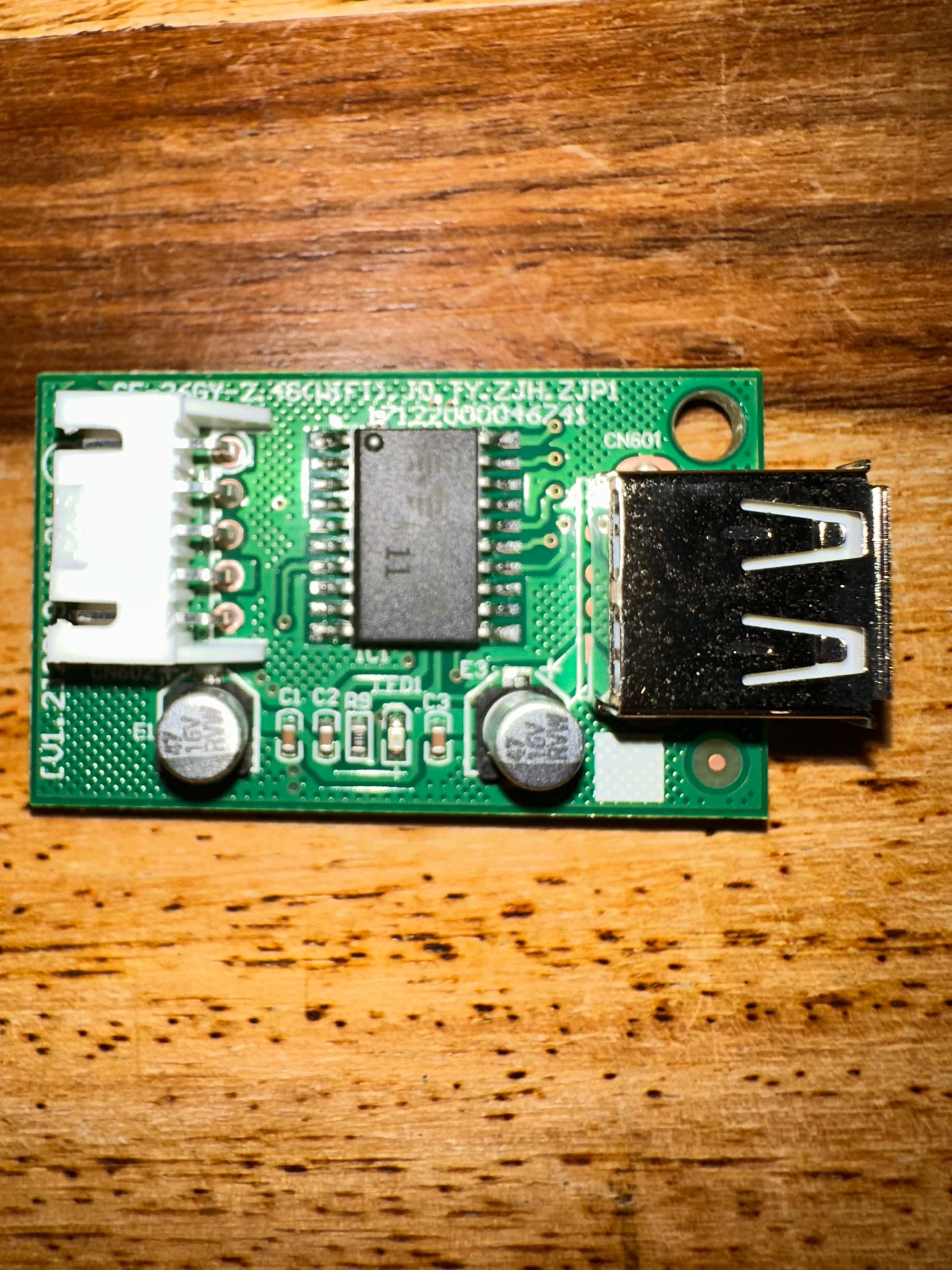
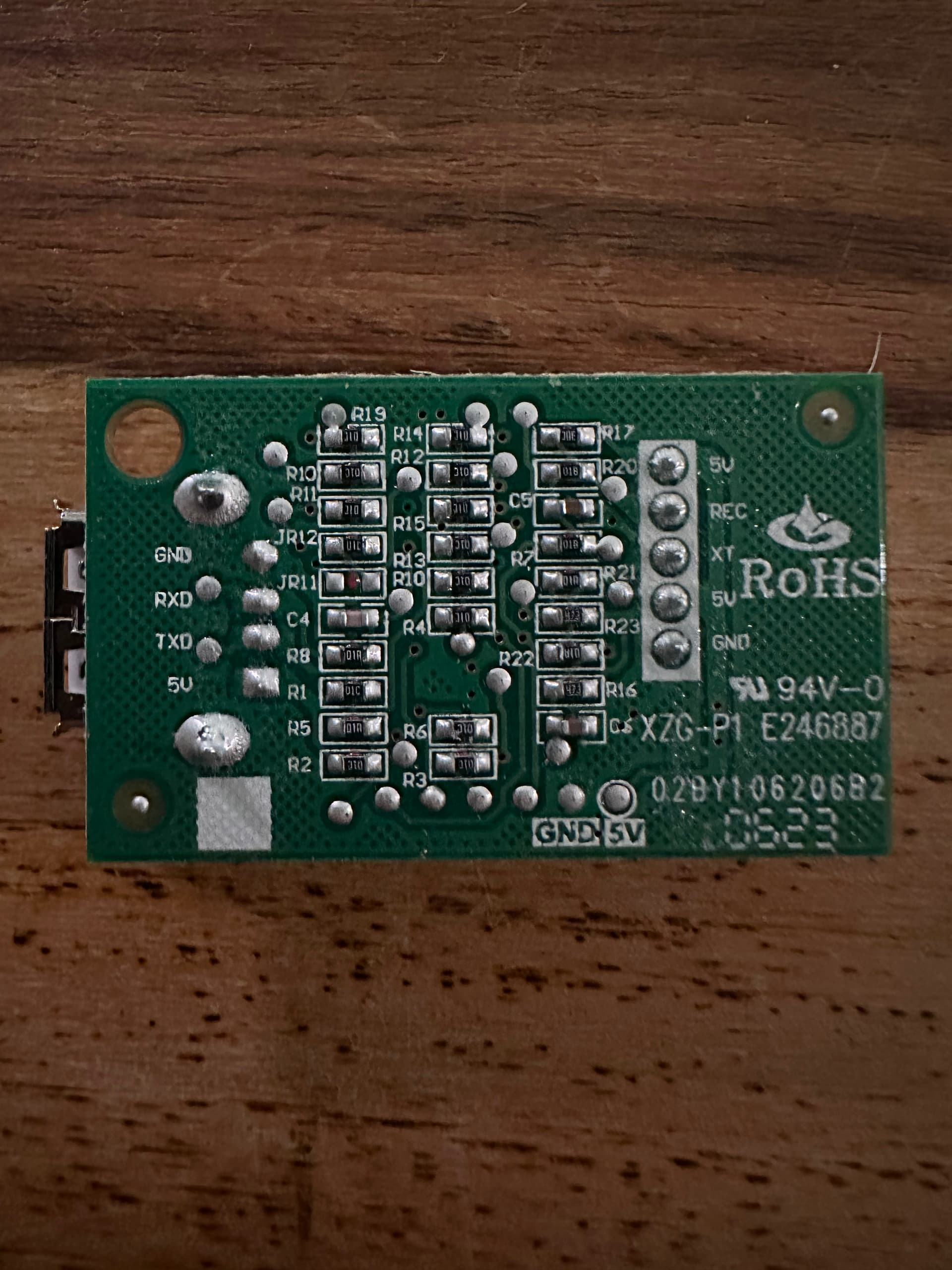
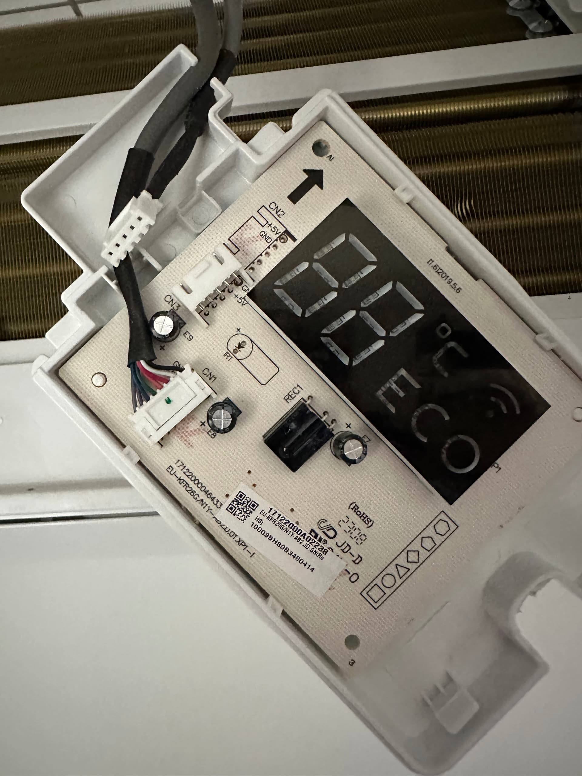
Jared I had the board with my OLMO minisplit (eukfrg26g)
I swapped the display with a ksaif0101aaa display board. it has wifi built in and it worked. it was an easy swap.
1 Like
Hi all. I struggle a bit to get my Vivax AC running. The Brand is produced by Midea as I can control it via the MIDEA LAN Integration without issues. I have the “coded” USB Stick as well but this isn’t really the issue. The Stick is connected to the additional “wifi breakout board” which is connected to Display Board via a Five-run cable
I exchanged the original Stick with a SLWF-01 Pro 2.1. It connects to the AC but it got no reading of power and humidity. Also I can’t switch off the display, toggle the “beep” or activate swing modes.
UART setup in the original YAML is this:
uart:
  tx_pin: 12
  rx_pin: 14
  baud_rate: 9600
I tried to switch the pins and I tried pin 1 and 3 as well.
I´m at the end of my knowledge plus Vivax seems to be the less known brand of the “Midea Line-Up”. Anyone have an idea what I could try as well?
Power and humidity may not be reported (my ACiQ reports power but NOT humidity). I believe toggling the display and some other settings can only be done via IR and not UART.
1 Like
I also have Vivax and SLWF-01 Pro 2.1 combination. My AC does not report current power or humidity, but with stock adapter I had Total energy consumption.
This is my solution…
You can keep usb log disabled
logger:
  baud_rate: 0
Create sensor
sensor:
  - platform: template
    id: midea_total_energy_kwh
    name: "AC Total Energy"
    unit_of_measurement: "kWh"
    device_class: energy
    state_class: total_increasing
    accuracy_decimals: 0
I don’t care about decimals, but if you do it is not enough to change this value, because down in UART debug code I’m dividing int on purpose. The idea was to get whole number and publish only after value is increased by 1 or more.
uart:
  id: midea_uart
  tx_pin: 12
  rx_pin: 14
  baud_rate: 9600
  debug:
    direction: RX
    after:
      timeout: 50ms
      bytes: 32
    sequence:
      - lambda: |-
          static std::vector<uint8_t> buf;
          static int32_t last_pub = -1;
          buf.insert(buf.end(), bytes.begin(), bytes.end());

          while (buf.size() >= 2) {
            if (buf[0] != 0xAA) { buf.erase(buf.begin()); continue; }

            uint8_t len = buf[1];
            size_t frame_len = (size_t)len + 1;
            if (buf.size() < frame_len) break;

            std::vector<uint8_t> frame(buf.begin(), buf.begin() + frame_len);
            buf.erase(buf.begin(), buf.begin() + frame_len);

            auto it = std::find(frame.begin(), frame.end(), 0xC1);
            if (it == frame.end()) continue;

            size_t c1 = (size_t)std::distance(frame.begin(), it);
            if (c1 + 7 >= frame.size()) continue;

            size_t i = c1 + 5;
            uint32_t raw = ((uint32_t)frame[i] << 16) | ((uint32_t)frame[i + 1] << 8) | (uint32_t)frame[i + 2];
            int32_t total_kwh = (int32_t)(raw / 1000);

            if (last_pub < 0) {
              last_pub = total_kwh;
              id(midea_total_energy_kwh).publish_state((float)total_kwh);
              continue;
            }

            if (total_kwh >= last_pub + 1) {
              last_pub = total_kwh;
              id(midea_total_energy_kwh).publish_state((float)total_kwh);
            }
          }
Beeper:
switch:
  - platform: template
    id: beeper_sw
    name: Beeper
    icon: mdi:volume-source
    optimistic: false
    turn_on_action:
      - midea_ac.beeper_on
    turn_off_action:
      - midea_ac.beeper_off
For swing, try to put this
climate:
  - platform: midea
    ...
    supported_swing_modes:
      - VERTICAL
      - HORIZONTAL
      - BOTH
    ...
1 Like
Thanks Jason. I can disable display and beeper via the cloud integration. So should be doable like @mihten provided a few hours ago. I have two Vivax Models installed. Three Design R and two “Floor” units. The Floor units report at least humidity but I would be more happy about the power usage as I would be need it to include it into my automations
This looks promising! So just for my rudimental understanding you extended the YAML of the ESP-Home component, correct?
When you say you don’t get the current power reported but the total is it completely ruled out or might there be a way to extract it as well? As said. I´m no expert and rely heavily on you geniuses here and a bit on gemini/claude when it comes to YAML and stuff ![]()
Ok, you got me… I’m not smart either ![]()
This was 99% GPT-5.2. According to that guy, my device is not reporting current power. If it’s not aware of current power, my assumption is that this total used energy is only an estimate based on parameters like max rated power, current mode, fan speed, temperature…
If you need accurate and reliable power metering, I’d use something like Shelly PM ( just an example, I don’t have a clue how accurate is shelly). That way you would also have a mean to cut AC from power network easily, if needed.
Here is my complete config: https://pastebin.com/raw/v5G3qBc2
Large parts are just commented out because I don’t yet have prerequisites to implement them.
Has anyone modified their midea AC to relocate the integrated temperature sensor on the outside of the unit? The sensor seems to be pretty inaccurate and I’m wondering if extending it’s wires 6" and poking it through some hole will alleviate this delta. The sensor reports hot when the minisplit in another room is on, I would have thought they thought through this based on the number of multi head systems they sell…
Does anyone know where the sensor is? Is it PCB mounted or somewhere in the airstream?
Thanks! Glad to hear you managed to find a solution.
In my setup, there is a water pump between HP and AC units, so I only need to monitor AC units’ state (on/off/heating/cooling) in order to start/stop water pump and switch HP between heating and cooling modes. As I understand reading internal AC bus is the only way to get desired info
Hey @ChasakisD, I finally made it work ![]()
TL;DR: wrong default unit address, DIP switch on the board is 0x30 (48), not 0 as I had assumed.
XYE protocol on my MKG-300-C unit also turned out to be slightly different.
BTW, I wrote a simple agent to investigate it, GitHub - egort/mdv-fancoil-agent
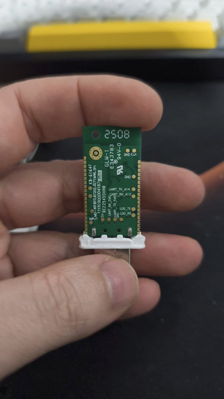
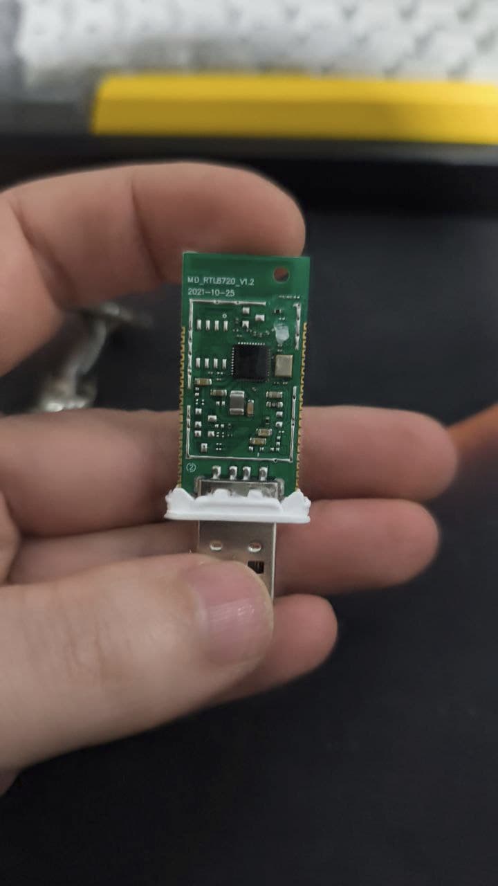
Hi Guys, someone have luck with Jocel Air ?
In his board I can see these codes:
CEM-1:S3110 and 94V-0 and E173873
Currently I have a dongle from JOCEL but… this dongle does not integrate with HA.
This is the original dongle.
Hi everyone. I’m just starting with these things, and I don’t know if I have to give up ![]() #
#
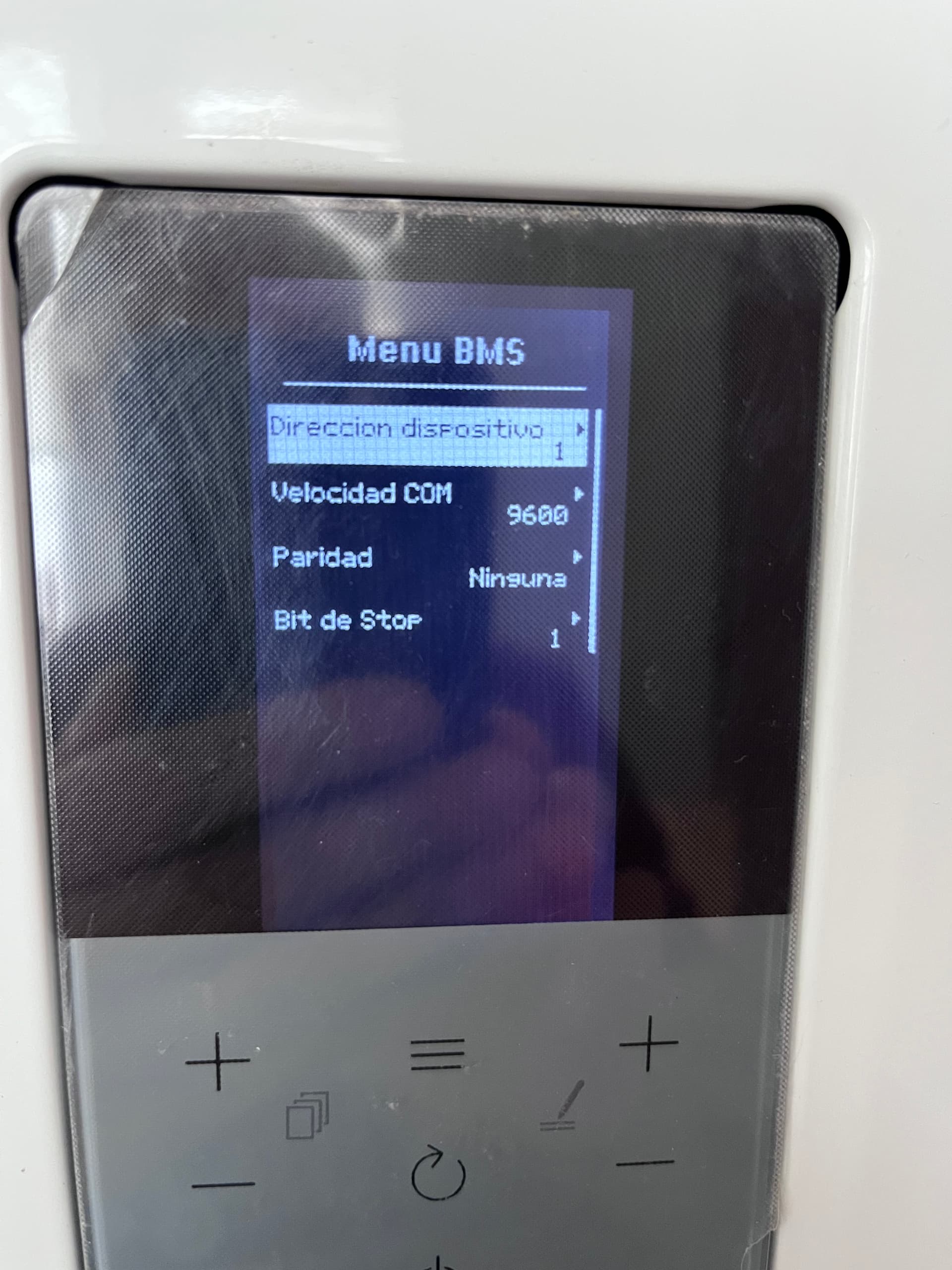
Summary of what I’ve tested and why Modbus is not working (Ferroli Omnia ST 3.2 + LilyGo T-CAN (ESP32+RS485)
I’m trying to read Modbus RTU from a Ferroli Omnia ST using an ESP32 (LILYGO T-Relay). According to the official wiring diagram, Modbus should be available on the terminal block labeled A–B–E.
Here is everything I’ve verified so far:
1. Wiring matches the official Ferroli schematic
- The SCP05 display is connected to the main board through CN14 using the 7‑pin connector (A, B, X, Y, +, −).
- From the SCP05, three wires (yellow, green, purple) go to the terminal block labeled A–B–E, exactly as shown in the official diagram.
- There are no missing cables and nothing appears disconnected.
2. The SCP05 is the correct model
- It is the SCP05.011 (FW 2.03), the same model referenced in the documentation.
- There are no additional connectors or RS‑485 modules inside the SCP05.
- The SCP05 PCB does not contain any RS‑485 transceiver (MAX485, SN65HVD, etc.).
3. BMS/Modbus configuration menu exists
- You can configure it but there is no option to enable/disable BMS or Modbus, unlike other Ferroli products.
4. Modbus communication tests
- ESP32 configured as Modbus master: 9600 baud, 8N1, address 1.
- I only receive no response to any request
- Swapping A/B does not change anything.
I’ve been able to flash my esp32 and can connect and start but there is no answer from my Ferroli ![]()
I’m using a RJ45, orange and white-orange for A and B and green for E.
Can someone have a look into this?
Thanks a lot for your help.

Great work! Can’t wait to try it. Do you have any plans for an esphome component? Getting 5v to power up on esp is very easy as you can take it from the controller. So it would be great to have an esp32 inside the fan coil unit in ordet to control it!
Guys, is there any solution to use external HA temperature sensor with 0.1C precision? IR transmitter method does use integer values ![]()
May be connect esphome directly to internal temperature sensor?
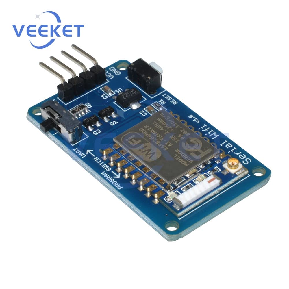
Were able to connect my MDV AC using a 5v uart board like that one:
Too bad I can’t tutn off AC’s display from it without adding an IR but that’s a problem for future me I guess. Thanks everyone who researched and developed this wonderful esphome module
Thanks for your work!
I’ve tried to make an order on JLCPCB using the production files from your repo, but there are some errors:
- uploading the gerbers hangs some time at 96% and when it’s loaded, it can’t detect the board dimensions. This should be detected from the gerber files automatically, so not sure what’s wrong there (tried multiple browsers, different times). Some dimensions are required if you want to add PCBA so I typed 30x60 just to move on.
- then when I upload BOM and CPL it fails to accept the CPL file

Do you have some other prod files which are working?