My Smart Home Build

There weren’t too many notable hiccups. I did have a one motion detector that must have had a wire screwed or stapled through, because it doesn’t work. That’s been the only thing I can think of. I’ve been pleasantly surprised at how fast the automations work. I have a few doors that HA turns the lights on when they open. For the first few weeks my wife kept asking who was leaving the lights on. The automations work so fast that by the time the door is cracked the light is on and you can’t tell that it’s being turned on by HA.

I wish I would have hardwired temp sensors into each bedroom, or maybe each room. Mainly because I’m having some HVAC balancing issues in our bedrooms that are requiring me to use remote WiFi temp sensors that connect to my thermostat to average the temps. I would have ran wired remote temp sensors to the mech room then ran a Cat6 from the thermostat to the mech room so I’d have more options. I also wish I would have run a wire to my doorbell chime so I could more easily get a doorbell trigger in HA.

Nice write up.

It really sucks that Google discontinued the ChromeCast Audio, making you use Ultra’s with audio extraction. I was lucky enough to buy a few as the last stocks were being sold.

It took me a couple of seconds wondering why you had compressed air connected to the irrigation… then thought, hmm frozen pipes in winter. Not something we have to worry about in Australia!

1 Like

This is amazing!

1 Like

Nice writeup!

The board does not seem to be able to measure mains voltage, so I don’t think you’ll be able to get real power (watts). You could estimate the apparent power (VA) by multiplying RMS current by nominal phase voltage, but you won’t be able to measure the power factor.

Amazing write up! I’m in the early stages of building my own house and this is insanely helpful!

I was wondering if you could detail when/how/where you installed the door sensors?

Also where’d you place each motion sensor and what advice do you have there?

Thanks again!

Glad it’s helpful!

Talk with your contractor about the door sensors. I ran the wire (22/2 wire, I recommend oxygen-free copper wire. It needs to be in-wall rated. I used this) to each door I wanted a sensor on (pretty much all of them) during the electrical rough in stage. I drilled a 1/2" through the framing (not the door, just the 2x4 rough framing) and dropped 3 feet of wire through each hole, then rolled it up out of the way.

If I knew which way the door would swing I put the hole on the side of the door where the handle would be. If I didn’t know I put the hole in the middle of the door frame. There’s enough room between the rough framing and the door frame for the wire to be routed to the correct side of the door. My trim guys installed the doors, I gave them a door sensor so they knew what size hole to drill (I think it was 3/8"). They drilled the hole in the door frame and pulled the wire through. I came back after paint to install the door sensor. Although, you could probably do it before paint and just as they get the doors hung. If they are going to spray foam around the exterior door frames I recommend getting the sensors in before that step.

Here’s what the sensor looks like, it’s very hidden. The top of the door also get’s a 3/8" hole and the other half of the sensor (it’s just a magnet). You can also see a ceiling-mounted motion detector in the ceiling near the attic hatch.

Here’s my wiring schematic and my ESPhome code. I only show one door sensor, but the optocoupler and ESP32 will handle 16 of them. Just run a wire from the optocoupler to a separate ESP32 GPIO for each sensor. run the hot wire from each + input on the optocoupler to the next. Then run a separate ground wire from the 12v power supply (I used this distribution block) to each door sensor. Do not run in series from one door sensor to the next, run separate wires.

esphome:
  name: binary_sensor_board_1
  platform: ESP32
  board: nodemcu-32s

wifi:
  ssid: "Basement_AP_IoT"
  password: "YOURPASSWORD"
  #Static IP
  manual_ip:
    static_ip: 192.168.1.101
    gateway: 192.168.1.1
    subnet: 255.255.255.0
  #Turn Off Power Save Mode
  power_save_mode: none
  fast_connect: on

  # Enable fallback hotspot (captive portal) in case wifi connection fails
  ap:
    ssid: "binary-sensor-board-1"
    password: "YG6ZvkWHIdDt"

captive_portal:

# Enable logging
logger:

# Enable Home Assistant API
api:

ota:

binary_sensor:
#Terminal 1
  - platform: gpio
    pin: 
      number: GPIO23
      mode: INPUT_PULLUP
    name: "Kassidys Door"
    device_class: door
#Terminal 2
  - platform: gpio
    pin: 
      number: GPIO22
      mode: INPUT_PULLUP
    name: "Front Door"
    device_class: door
#Terminal 3
  - platform: gpio
    pin: 
      number: GPIO21
      mode: INPUT_PULLUP
    name: "Toy Room Door"
    device_class: door
#Terminal 4
  - platform: gpio
    pin: 
      number: GPIO19
      mode: INPUT_PULLUP
    name: "Office Door"
    device_class: door
#Terminal 5
  - platform: gpio
    pin: 
      number: GPIO18
      mode: INPUT_PULLUP
    name: "Garage Closet Door"
    device_class: door
#Terminal 6
  - platform: gpio
    pin: 
      number: GPIO5
      mode: INPUT_PULLUP
    name: "Garage Entry Door"
    device_class: door
#Terminal 7
  - platform: gpio
    pin: 
      number: GPIO17
      mode: INPUT_PULLUP
    name: "Mud Room Laundry Door"
    device_class: door
#Terminal 8
  - platform: gpio
    pin: 
      number: GPIO16
      mode: INPUT_PULLUP
    name: "Grocery Door"
    device_class: door
#Terminal 9
  - platform: gpio
    pin: 
      number: GPIO32
      mode: INPUT_PULLUP
    name: "Garage Service Door"
    device_class: door
#Terminal 10
  - platform: gpio
    pin: 
      number: GPIO33
      mode: INPUT_PULLUP
    name: "Powder Bath Door"
    device_class: door
#Terminal 11
  - platform: gpio
    pin: 
      number: GPIO25
      mode: INPUT_PULLUP
    name: "Kids Toilet Door"
    device_class: door
#Terminal 12
  - platform: gpio
    pin: 
      number: GPIO26
      mode: INPUT_PULLUP
    name: "Kids Bathroom Door"
    device_class: door
#Terminal 13
  - platform: gpio
    pin: 
      number: GPIO27
      mode: INPUT_PULLUP
    name: "2nd Floor Guest Closet"
    device_class: door
#Terminal 14
  - platform: gpio
    pin: 
      number: GPIO14
      mode: INPUT_PULLUP
    name: "2nd Floor Guest Door"
    device_class: door
#Terminal 15
  - platform: gpio
    pin: 
      number: GPIO04
      mode: INPUT_PULLUP
    name: "Beyer Closet Door"
    device_class: door
#Terminal 16
  - platform: gpio
    pin: 
      number: GPIO13
      mode: INPUT_PULLUP
    name: "Beyer Door"
    device_class: door

For the motion detectors, run a 22/4 wire (same wire I linked to above, just get the 22/4 version). If you use a combination motion/glass break sensor you will need 22/6 wire, or probably just use a Cat6. The wiring schematic is the exact same as the door sensors except you also need to send the motion detector 12v power. So 2 wires handle the 12v power for the sensor, the other 2 wires take the ground wire from the power supply to the sensor and back to the optocoupler. The motion sensor either opens or closes that circuit when it sees motion. A single 12v power supply of about 2amps should easily handle all your sensors.

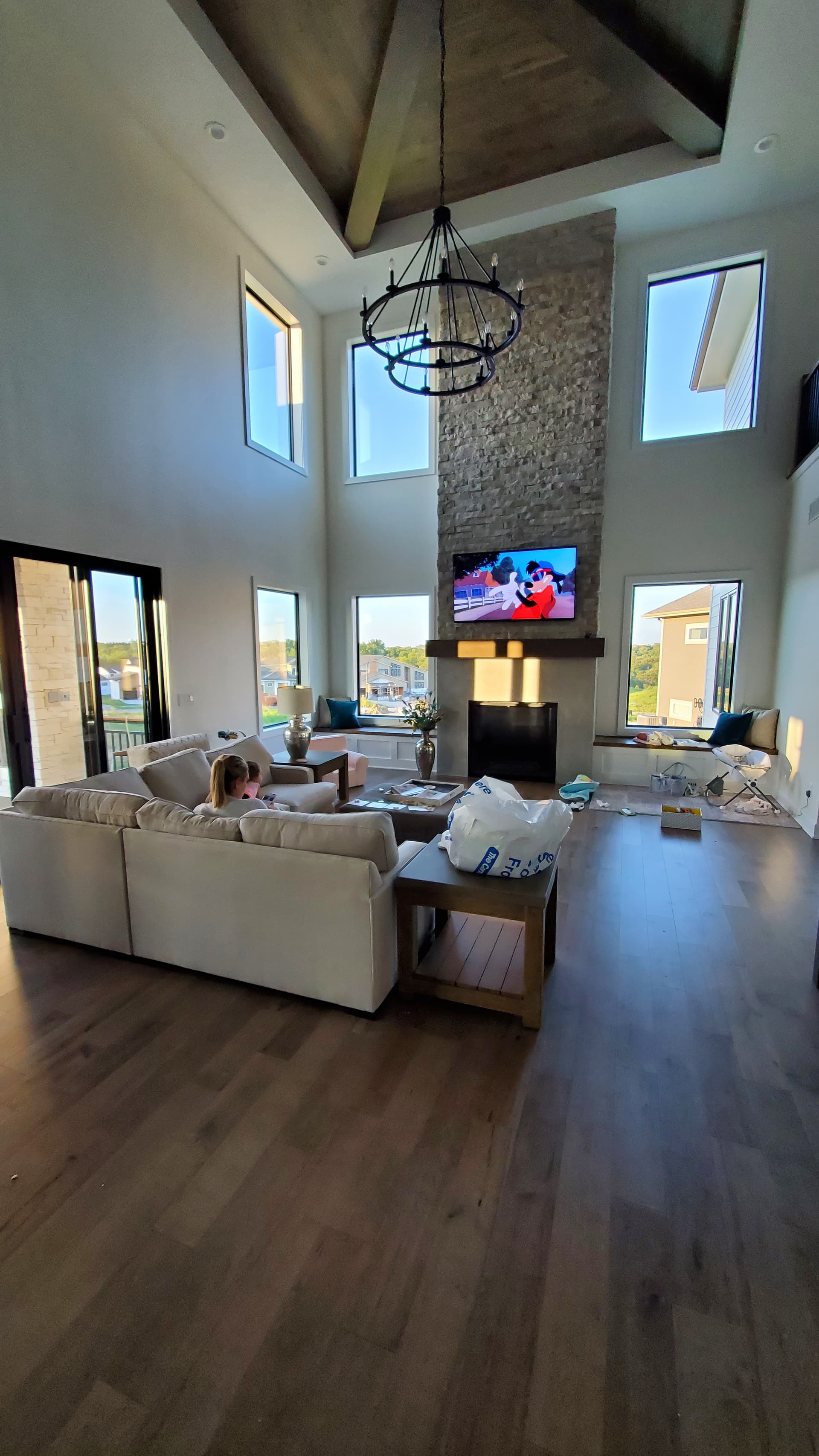
For placement, I tried to put them in areas where I thought it would be helpful to see motion (duh!), for the wall-mounted sensors I hung them between 7-8 ft off the floor and always in a corner. For the ceiling mounts, I tried to put them somewhat centered in the space, but I also paid attention to how they would look (like centering them between lights). Try to keep them away from heat sources, like lights and HVAC air supplies and out of direct sunlight.

For wall-mounted, I just put a small screw in the corner of wall and wrapped the wire around it. The drywall guys pulled the screw out (use a phillips head to make it easy on them) and pulled the wire through the drywall. This is the best example I could find.

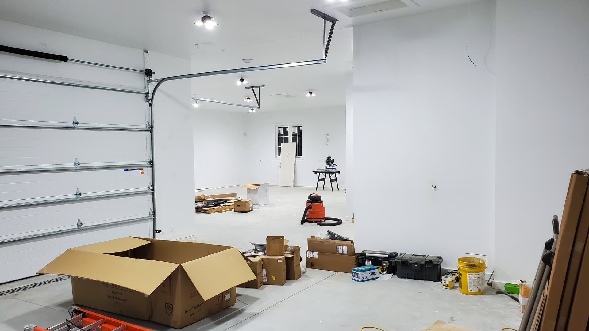
For ceiling-mounted, screw or nail a 2x4 between the joists, put a 1/2" hole in the 2x4 and drop 2 feet of wire through the hole. The drywall guys will cut a hole and pull the wire through. Similar concept to what I did with this pipe, but put a wire through the hole.

I hope that helps!

1 Like

Thanks @bphillips921, that was what I was looking for! I also seem to have a flexible builder who will let me get in and install low voltage items myself.

Also for your pumps/power measurement, I recently picked up the cheap Emporia Vue ($150) and installed ESPHome per these instructions. It’s a 16 channel power meter with individual 50 A CT Clamps + 2 main phase 200 A CT Clamps with voltage monitoring on each phase. It is a fantastic way to monitor power.

Thanks for the tip, I’ll look into that!

@bphillips921 Brad, Can you clarify how you have these temperature sensors included in the concrete? They are going to be pouring our basement slab this week and was curious if this was something you actually embedded in the concrete or if it was just on the surface?

Thanks!

There are two ways to do it. For my basement slab, I just drilled a hole after the fact. I used a FLIR camera to see the pex tubing in the floor then drilled the hole about 2" deep in the middle of a loop. I filled the hole with this conductive paste before inserting the DS18B20 probe. If I were to do it again, I would have stuck a straw or something in the foam board and above where the top of the concrete would go. That way I wouldn’t have needed the FLIR, I could have perfected where to put it and I could safely go deeper with my hole.

For the garage, I wasn’t going to have a good place in the slab to drill a hole, so I took a 15ft long piece of PEX pipe, duct taped the end, and stapled it to the foam board in the middle of a loop. I then pushed my probe into that piece of PEX.

Both methods seem to be equally accurate as far as reading temps.

1 Like

Awesome project. Would love to see some pics of the actual house if you’re comfortable with that! So many ideas for when (if?) I ever build a house from scratch!

I suppose there is no harm in that. Here are some exterior pictures


A few interior
Patio

Great Room

Garage (1,800 sq ft, my favorite room in the house :grin:)

Our builder has some other pics on his website from when the house was almost done. We are missing our big fridge and backsplash in these pics, but I think most of the other stuff was done.
http://www.arkoscustomhomes.com/scenicview.html

5 Likes

Absolutely amazing! Dream home!

1 Like

@bphillips921 your project is great, cheers!

I have a question: where did you buy these screw terminals?:

I got them on Amazon

1 Like

@bphillips921 I have another question, if I may.

You wrote:

I use a 8 channel relay and ESP32 with ESPhome to automatically switch to the TV as an input when the TV is playing.

Can you write more - what exactly the relays are connecting?

I.e. can you achieve that your audio source #1 is playing on speaker A, while at the same time source #2 plays on speaker B?

Maybe you could share the schematics?

Thank you!

I’ll do my best to explain it. It gets a little messy.

First, the parts needed.
3D printed case

ESP32

8 channel relay

RCA keystones

RCA terminals

ESPHome Code

esphome:
  name: rca_switch
  platform: ESP32
  board: nodemcu-32s

wifi:
  ssid: "Basement_AP_IoT"
  password: "PASSWORD"
  #Static IP
  manual_ip:
    static_ip: 192.168.1.111
    gateway: 192.168.1.1
    subnet: 255.255.255.0
  #Turn Off Power Save Mode
  power_save_mode: none
  fast_connect: on

  # Enable fallback hotspot (captive portal) in case wifi connection fails
  ap:
    ssid: "Rca-Switch Fallback Hotspot"
    password: "sSN6czO4UzZa"

captive_portal:

# Enable logging
logger:

# Enable Home Assistant API
api:

ota:
  password: "PASSWORD"


switch:
  - platform: gpio
    pin: GPIO23
    name: "Garage Speaker Switch-Right"
    icon: "mdi:speaker"
    restore_mode: ALWAYS_OFF
    inverted: true
  - platform: gpio
    pin: GPIO22
    name: "Garage Speaker Switch-Left"
    icon: "mdi:speaker"
    restore_mode: ALWAYS_OFF
    inverted: true
  - platform: gpio
    pin: GPIO21
    name: "RCA 3"
    icon: "mdi:speaker"
    restore_mode: ALWAYS_OFF
    inverted: true
  - platform: gpio
    pin: GPIO19
    name: "RCA 4"
    icon: "mdi:speaker"
    restore_mode: ALWAYS_OFF
    inverted: true
  - platform: gpio
    pin: GPIO18
    name: "RCA 5"
    icon: "mdi:speaker"
    restore_mode: ALWAYS_OFF
    inverted: true
  - platform: gpio
    pin: GPIO5
    name: "RCA 6"
    icon: "mdi:speaker"
    restore_mode: ALWAYS_OFF
    inverted: true
  - platform: gpio
    pin: GPIO17
    name: "RCA 7"
    icon: "mdi:speaker"
    restore_mode: ALWAYS_OFF
    inverted: true
  - platform: gpio
    pin: GPIO16
    name: "RCA 8"
    icon: "mdi:speaker"
    restore_mode: ALWAYS_OFF
    inverted: true

Here is the wiring schematic. One relay will control 2 inputs and one output. So, for stereo sound left and rigth you will need two relays.

  • Connect the “-” terminals for all 3 RCA jacks on each speaker side (RCA input 1 Left, RCA input 2 Left, and RCA output Left). Repeat for right inputs and outputs.

  • Connect the RCA outputs to the middle “common” terminal on the relay. Connect the left output to one relay and the right to the other

  • Connect RCA input 1 to the “NC” on the relay. Connect the left to one relay the right to the other.

  • Connect RCA input 2 to the “NO” on the relay. Connect the left to one relay the right to the other.

With this setup you can individually trigger the left and right relays, so you could have input 1 playing through the left speaker and input 2 playing through the right. I use my script in HA to always change GPIO23 and GPIO22 at the same time so that both speakers play the same input. You could also hardwire this by soldering a “Y” wire that goes from one GPIO pin on the ESP32 to 2 input pins on the relay that you always want to switch together.

Hopefully that helps.

Thank you.

So in your drawing the “Output L” and “Output R” are two speakers. What are the “Input 1” and “Input 2” - are they two separate physical amplifiers?

How do you add a 3rd, 4th, more speakers to the same Input? (e.g. you want to broadcast a message to all speakers in the house).

The “Output L” and “Output R” are RCA outputs. They plug into the input of an amplifier. The speakers plug into the amp output. So it goes: Input audio device (chromecast, tv, etc) > RCA switcher > amp > speakers.

The “input 1” and “input 2” can be any audio device that uses RCA. In my case, input 1 is a Chromecast device (chromecast device is plugged into an HDMI > Audio extractor) and input 2 is the TV in my garage.

You could “Y” the output L and output R into multiple amp inputs then hook the speakers into those amp channels. For example, I use this amplifier. Each channel handles 1 speaker and there are 2 channels per zone. So, if I wanted two speakers in the garage and two speakers in the living room to always play the same thing I would “Y” the output L and output R cables from the RCA switch box into zone 1 and zone 2 input. Then I would hook the garage speakers to zone 1 and living room speakers to zone 2. Or, in the case of my amp I linked to, it has 2 Bus inputs. So I could hook my output L and output R to the Bus 1 in on the amp then set zone 1 and zone 2 to use bus 1 as the input source.

1 Like

This was great to read. Thank you for sharing your journey and definitely giving me ideas of what to do next. It took me 5 years to make my home smart, slowly and gradually buying different things. Please keep sharing your updates or if any of the things you used didn’t work out. I am actually thinking about buying few of the hard-wired sensors you used.

Also how long did it take you to set all the things you mentioned? I am very curious.