@brystmar I don’t have a hot button pcb installed, and I wonder if one is even needed when, assuming it’s possible, one is controlling it via HA. I will look into getting one to see what is sent over the 485 bus but first I need to figure out how to sniff the traffic, and ideally have both the Navilink and the ESPHome connected. I don’t have much experience with this and neither a lot of time to dedicate to it.
@tsquared I was wondering why the temperature setting, which should be a set and forget setting, uses the climate controller? I believe it adds unnecessary complications and believe it would be best accomplished with a simple number input. I will likely try that when I get a moment to do so.
Oh I wasn’t suggesting a physical button. Any HA entity that can function as a soft button would be great. I’d love to build an automation that tells the Navien to start heating water immediately, without needing to open a hot water tap first. That’s what I assumed the HotButton feature accomplished. I’m still learning here, so it’s entirely possible I am misunderstanding both HotButton and the existing config.
Agreed on the climate entity btw. Changing this also allows us remove the fake switch too, right?
Isn’t HotButton primarily useful with external recirculation feature? It basically triggers recirculation “when needed” instead of being constantly on (which would be wasteful most of the time).
At the push of a button, the Navien HotButton activates the internal recirculation pump and gas fired burner to heat water in supply lines. This gives your customers hot water when they need it, saving water and money.
@brystmar you probably did find a typo/conversion rate inconsistencies. Funny enough - As @dasp points out I think I found about 10 different conversion rates for that depending on where I looked. I think I may have ended up using one from one of the online converters, but it (or maybe, I) rounded to 3 decimal places. Unfortunately, I am unable to recall. I thought I did good with the notes added, but of course - I wouldn’t have a source for the items in question!
@dasp I’ll have to go back and check - I may have inadvertently copy/pasted the comment, but changed the multiply/divide number - even though the metric items are the standard units that come from the device. Oops - I’ll have the check that and edit the original post.
@aruffell@brystmar The temperature setting was an idea - the thought behind it was: it really is a “temperature control device” - So, I went with the climate controller where I was going to try and incorporate both the setpoint temperature, as well as the enable/disable into one single that climate controller. Which would have provided a nice thermostat type setting for the lovelace dashboard. However, once I realized that it would/could technically “shut off” when reaching temperature, I then decided to go a different route - hence - the “fake switch” I did try to utilize a swipe and type box for the setpoint - though I was unsuccessful, So, I left it as it was because I was a bit stumped and I wanted to get a rough copy out there to continue this discussion! So thank you for asking the question! Now I’m really interested in what others have used for Hot Water Heater setpoints? Slider/Swipe n Type/climate controller, etc?
For modifications moving forward, this is what I think I heard so far.
Confirm/Revise the multipliers and the respective comments.
Remove climate controller, and provide different interface to adjust setpoint.
Remove “fake switch” as it would no longer be necessary.
Anything I missed?
I am definitely appreciating all the interaction here! This is great! My M5 Stack with the 485 board just showed up, so I hopefully can create a work of art just the way @aruffell has!
AI Disclaimer: I got this answer from ChatGPT and have not researched it to verify how correct it is, BUT it sounds completely reasonable and would 100% explain why there isn’t a single standard constant:
The conversion from cubic meters of gas to therms is not entirely straightforward or standardized because it depends on the specific energy content of the gas being measured. Different types of natural gas have varying calorific values, meaning the amount of energy contained in a cubic meter of gas can differ based on its composition.
It also stated that natural gas may contain other gasses which will affect the calorific value. This means that while there may be a constant for the main gas delivered to our home, it will likely never be accurate. I would check with the local gas company to see what value they use in their calculations if they include it on their bill. I am guessing they picked a number as the exact composition also likely changes. Either way, one could have a way for the user to enter the value in the YAML, or even in the device page to make it even easier.
I would likely just not have it at all as I only care about consumption and don’t have a use for “therms”. I guess if I had a choice to pick which gas composition to use, then it would be relevant.
I just checked my bill, and no trace of therms, but it may vary with region and/or supplier. This is what my bill looks like, and yes mine is in CCF too.
@aruffell@dasp This is interesting. While my provider does measure in CCF, they also show, and bill for therms. Interesting enough - you pushed me to find that they actually show the “therm factor” on my bill, or the conversion factor that they actually use - should make it a bit more accurate for the calculation at hand. My bill shown below for reference:
Full Disclosure regarding the calculations - I believe somewhere along the thread here - I was, and still am a bit unsure about some of these calculations and their accuracies so anyone who is more well versed at confirming these values - your help here is appreciated!
Also - due to this discussion, I think it may not actually be Therms anyway - but the CCF you are looking for. No? Anyway - I updated my config to now show all 3 values, cubic meters, CCF, & Therms. As a side note, to make life easier, You can change the
internal: False
to
internal: True
if you wanted to get rid of any of these from your display/lovelace dashboard.
Below is the updated portion of the template sensors for all of these.
- platform: template
    name: "Total Gas Use Cubic Meters"
    id: total_gas_use_m3 # divide by 2.832 to get CCF
    icon: mdi:gas-cylinder
    unit_of_measurement: m³
    accuracy_decimals: 1
    internal: False
  - platform: template
    name: "Total Gas Use CCF"
    id: total_gas_use_ccf # this is derived from the entity Total Gas Use Cubic Meters and converts to CCF for comparison to US energy bills.
    icon: mdi:gas-cylinder
    unit_of_measurement: CCF
    accuracy_decimals: 1
    internal: False
    lambda: |-
      return (id(total_gas_use_m3).state/2.832);
  - platform: template
    name: "Total Gas Use Therms"
    id: total_gas_use_therms # this is derived from the entity Total Gas Use CCF and one of the typical measurements for the utility company to bill against in the US.
    icon: mdi:gas-cylinder   # this multiplier 1.02845 was obtained from my energy bill - it is known as "Therm Factor" on my bill
    unit_of_measurement: therms
    accuracy_decimals: 1
    internal: False
    lambda: |-
      return (id(total_gas_use_ccf).state * 1.02845);
I edited this post to correct myself as I incorrectly thought CCF and ft³ were the same. I then discovered that 1 CCF is 100 ft³. Anyway, my updated template now matches yours except for the fact I supposedly used a non rounded conversion rate.
Any idea whether I can have both the Navilink and the ESP32 connected? It would help for me to compare the numbers on both systems… Since there is no control, just reading values I would think it works. Has anyone tried?
Ok, so I’m highly interested in doing this too! I have a Navien NPE-240S and I already had an extra m5 Atom RS-485. Programmed it right up with @kkopachev’s config and it’s ready to go. However, when I connect it to the control panel, it either a. Doesn’t turn on when I turn it back on or b. Locks up and turns off until I disconnect it. No shorts, same pins as everyone else. Thoughts? I checked with my Fluke that I’m on the right 12v & Ground pins. It even happens without the RS-485 pins connected and just 12v & Ground.
@aruffell I do believe you should be able to have both of them connected. I currently have both my original Python code with appropriate USB/RS485 converter, and my ESP32 connected in parallel and I am not having any issues with the data being decoded by both.
@whizkidTRW Have you tried to just power up the ATOM RS-485 using 12VDC from a power supply, and not the HW heater? That may help diagnose the problem.
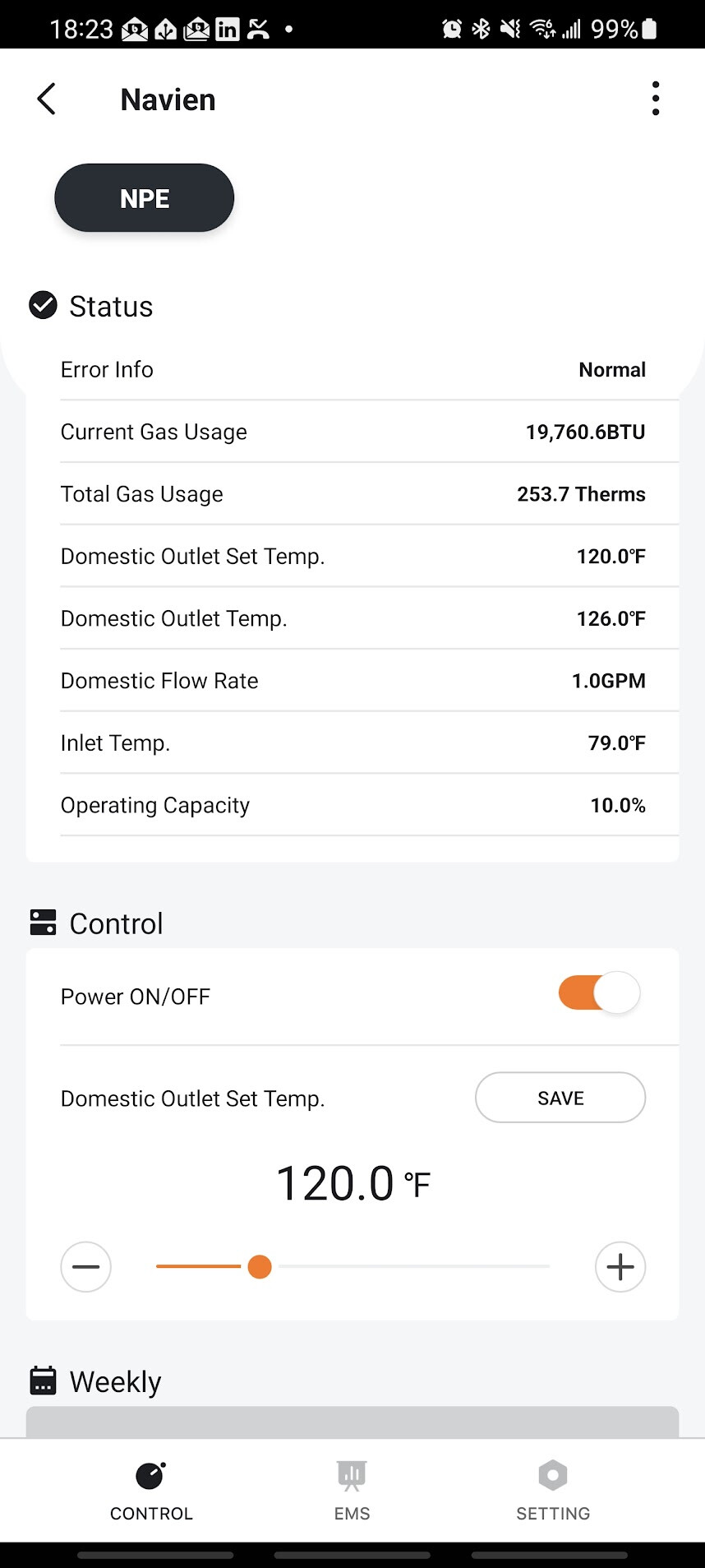
@tsquared - I have connected both the NaviLink and the ESP32 to the water heater. Both appear to be communicating fine. The Navien app appears to show less information than the last time I looked at it. For example I thought it showed CCF data but now it only shows therms which are useless given the constant used to calculate them is unknown and likely different than the one needed for my local supply.
I also made all template visible and found no matches between the Navien app and the ESP. Any idea why?
I also noticed an issue with the BTU. In ESPHome it is reported as kbtu/hr while in the Navien app it is just BTU. Therefore the 19,760.6 BTU should show as 19.76 kbtu/hr while instead it shows as 9.908 kbtu/hr.
I want to do more troubleshooting but I don’t know how to decode 485 serial messages.
One place to start is likely for me to set the water heater to metric so its app will hopefully also switch to metric and it will be easier to compare stuff.
Did you enable the NaviLink connection in the unit’s installer settings menu? Those of us who didn’t have a NaviLink device professionally installed probably need to do this ourselves. I noticed that step isn’t outlined anywhere in this thread, so I’ll save everyone the hassle of watching this youtube video.
It’s probably best to not have anyone in the house using hot water until you finish this setup process.
Unplug power to the Navien water heater. Remove the front cover using a P1/P2 Philips head screwdriver.
Insert the JST-XH(B) connector on the left side of the Navien’s main circuit board. On my NPE-240S, this connector is directly to the left of the (back arrow) button on the keypad. Note that this connector is keyed and should only insert one way. Ensure no wiring is exposed, and tuck the ESP away into an inside corner of the unit where it won’t touch (or be touched by) anything else.
Re-attach the front cover, and plug the Navien back in. Allow it to boot up and stabilize.
Press and hold the Menu and (back arrow) buttons simultaneously for 3 seconds. The service installer menu will appear. Choose option 1 to enter the installer menu and hit OK.
Default password is 1234. Enter this using the up/down arrow buttons, then hit OK.
Once inside the installer menu, select option 3 for Application Settings, hit OK.
Select option 1 for NaviLink, hit OK.
Select option 1 for NaviLink Connection, hit OK. You’ll see some text about the NaviLink system, hit OK again to continue.
Move the cursor up to select Enable under NaviLink Connection. Hit Ok.
Hit the (back arrow) button repeatedly until you exit all menu screens. The Navien will reboot and then purge the lines. Your ESP should now begin reporting data to Home Assistant.
I did this and now have the Navien’s data in Home Assistant. Big thanks to @tsquared, @aruffell, and others who contributed to this project! I learned a lot about esphome.
If you have an NPE-240A2 which comes with the HotButton board, there is a 12v / 5v / G screw down connector on the board that you can use to power the ESP separately. I have been using the 12V + G connectors to power a Zooz zwave multi-relay for the last year without issues.
Once my atoms arrive, I think it would be pretty safe to use the same to power those as well in case you do not want to power it from the primary RS485 connector.
I’m trying to wrap my head around the data I’m seeing for the “inlet” temp. I assumed the inlet and outlet temperatures measure water temp at the cold water intake and hot water output, respectively. That assumption may be wrong, at least for the inlet. Here’s what those looked like during this morning’s shower + breakfast routine:
Shower ran from 7:13 to 7:26. Our hot water target is 124ºF, and you can clearly see that from the outlet (purple) data.
I’m a bit confused about the inlet (blue) temp though. Our Navien lives in a utility closet with the furnace. That room is typically warm, so I’m not surprised its baseline temp settles ~74º. I am confused why it rises when the unit is running though. If this sensor truly measured the incoming water temp, I’d expect that to drop significantly as fresh water comes in from the city pipes. (Incoming water is nice and cold here in Seattle.). So this sensor must be measuring something else. Ideas?
For those of you looking to avoid building your own XH connector cable, and wanting to keep the Navlink Lite in place, another option similar to the RJ45 breakout shared previously is a dual RJ45 passthrough with breakout from amazon: Ethernet Passthrough Breakout
Other than using adding short ethernet cable from the breakout to the Navilink Lite, no crimping tools or special connectors required. Just make sure you check for +12V and G ( the outer terminals) .
@brystmar
I also noticed this with my NPE-240A2 . I kept my Navilink Lite connected and generally had approx 6 degree (F) difference between the Inlet Temp in the Navlink App and what is reported on HA from the ESP32.
It looks like there are actually two Inlet sensors on the A2, one that is on the cold water and the other at the Heat Exchanger.
The Navlink Lite is reporting at the Cold Inlet, while the ESP32 is reporting the temperature at the Heat Exchanger Inlet.
Both of temperatures can be seen on the basic status menu on the control panel .
You can see this in Installation Manual