Interesting. When I check over the last week on my unit, byte 8 is only ever 0 or 2. Regardless of the state of recirculation. It is 2 when a hot water tap is turned on, and zero when it is off.
interesting,
what model and firmware are you running on the navien.
i have:
NPE-210-A2
Main F/W v1.1
Panel F/W V2.2
do you have it on Hot Button or schedule? mine is on 1 day schedule right now.
I have a NPE-240A. How do you know your Firmware values? Can I get it from the front panel somehow?
The values I have I pull from the Gas data packet (here), it has a controller and panel value. I see:
Controller: v3.20
Panel: v0.31
I do not have the Hot Button panel installed (though I have one as I wanted to try it out, but then found that it wonât work in combination with the Schedule).
I have a schedule set via the Navien app + NaviLink 3 port controller.
On the A2 we have a full GUI for the controller so its just sitting in the menu.
so there might be a difference between what does what on an A vs an A2
im planning on using home assistant to press the hot button on a schedule also
My screen is very different and basic on the A model.
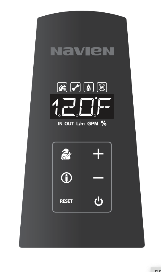
Searching the internet, I was not able to find anything that would help me find the Main and Panel FW Version on my 240A unit.
I asked ChatGPT and it told me to long press Info button and look at Technical Info values T.20 and T.21. Doing this only seemed to show 0.xxx â 9.xxx values. Canât go past 9.
I can check the R&D Information Menu by pressing + 3 times, - 3 times, then + 4 times, and picking 1.TEC (Technical information). When I check T.20 shows a value of 2 and when I check T.21 it also shows a value of 2. So I donât think they are the right fields.
Do you know if you get the values 1.1 and the values 2.2 from the corresponding Gas packet fields?
i havenât been able to find how to get the FW in the bytes yet.
there are a few values i think we should be getting but have not found them yet:
APS (analog pressure sensor) 0.38v to 0.40v
RPM 0-2000
Water Valve adjust 66%
Flame Value 5AD - 214AD
Exhaust Temp (air)
Thanks a lot! I am looking at it, trying to get the schematic out. In case if it is helpful, here is a version of your two images that combines the bottom traces with the top - makes it easier to follow traces.
I have the same Hot Button board, though mine came without the DIP switches.
From what I can gather, it seems that the key components are a voltage converter (U1/ AMS1117) that converts from 12V to 5V and a photo coupler (PC1) that electrically isolates the CON2/SIGNAL 2 from the Navien, so it canât damage it if the signal goes rogue. Some capacitors (CEx) for noise filtering.
Given the presence of AMS1117, I believe the main board only provides 12V DC.
There doesnât seem to be any specific logic on the board. I am guessing that the logic is all in the Navien and the board is only to separate the signals from the main board, and provide different voltages to power different Hot Button devices, eg RF remote.
Unfortunately, as I have a 240A not the 240A2 I canât dig through the data sent by the Navien to see what matches the values for the properties you mention.
So far, I have been able to determine that there are several counters - though I donât know what they measure. I determined that they are counters as the low byte seems to increment over time, and when it ticks over 255 (0xFF) the high byte increments.
Water(28) + Water(29)
is a counter
Water(30) + Water(31)
is a counter
Gas(28) + Gas(29)
is a counter - this one is tied to gas usage, as the more the gas is running the faster the increment.
Gas(30) + Gas(31)
is a counter
Gas(33) + Gas(34)
is a counter
Yup, matches my understanding. The Navien provides +13V. The AMS1117 provides +5V.
That 5V is used for several purposes:
a. Switches that feed back to the board - switch positions set various configurations and +5V is fed to corresponding pins of the big jack.
b. +5V is also used to feed the optocoupler based decoupling circuit - same thing, when CON2 or CON3 are shorted, +5V is delivered to respective pins.
That whole section of copper under the AMS1117 (from top view) is connected to +5V
All in all it comes to the fact that pins 8 and 9 from the left can take +5V as the âbuttonâ signal.
This is the Domestic Consumption Counter. I noticed that if I add up the number of times the hot tap is ON, aka domestic consumption is active (for me on my NPE-240A this is when byte 8
has a value of 3
) for each counter increment, there are 10 activations every time. That is, the counter increments for every 10 times that I consume hot water.
The Navien app has an EMS page, that shows a graph of daily values for Gas Usage or Domestic Usage Time or Domestic Usage Count or Hot Button Count.
I will test out the theory, but I believe that Domestic Usage Count comes daily
EndValue - StartValue
of the Gas(28)+Gas(29) counter.
I had a bug in my decoding code. I see a value of 32 for Byte 8 if a hot water tap is on, ie Domestic Consumption is active. I am not sure about a value of 8 as I was loosing the low bits of the data.
the summation values Iâve had a hard time identifying because I get wild values being reported, but an obvious trend line if i rule out the outliers.
for example gbyte 28+29 and gbyte 30+31,
they are obviously high/low byte increments, but i get some much garbage data
(again iâm not filtering checksums, maybe my connection is bad)
I donât have as much history as you do, only the last couple of days, but my set I donât have the outliers you see. Iâm logging checksum errors and allowing them through, but donât see any.
Here is the last few days for gas byte 30 & 31.
And I have maxâed out the number of times I can contribute to this discussion as a new user
I will start checking my code into GitHub so I can share my progress there.