I I just got an installed a ratgdo32 garage door opener controller. I got ESPHome installed on it and the device is showing on HA. However, it’s not reporting the correct state of the door and it can’t operate the door.
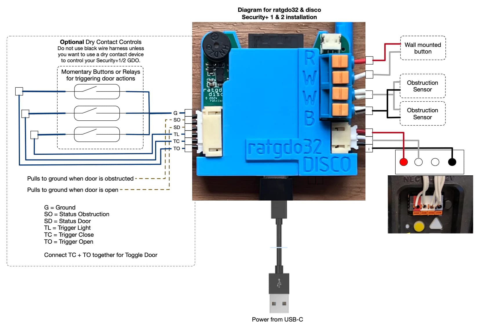
I think I may not have complete wiring but need to verify the requirements. Here is the diagram they provide:
All I have connected right now is the red, white, and black wires on the lower right. The button and obstruction sensor wires are connected to those same terminals. Do I read this correctly that I should disconnect them from those terminals and connect them to the terminals on the ratgdo32? I’m asking because I don’t want to disable my opener.
Also, even if those aren’t corrected correctly, shouldn’t the device be reporting the correct open/closed status? If so then I could use advice on how to troubleshoot.
Hi, I am new to Home Assistant (it’s up and I have my garden Ecowitt sensors in).
I just flashed my ratdgo32 with the fw for dry contacts.
and it is in HOA.
Now I am trying to figure our the wiring to the garage opener.
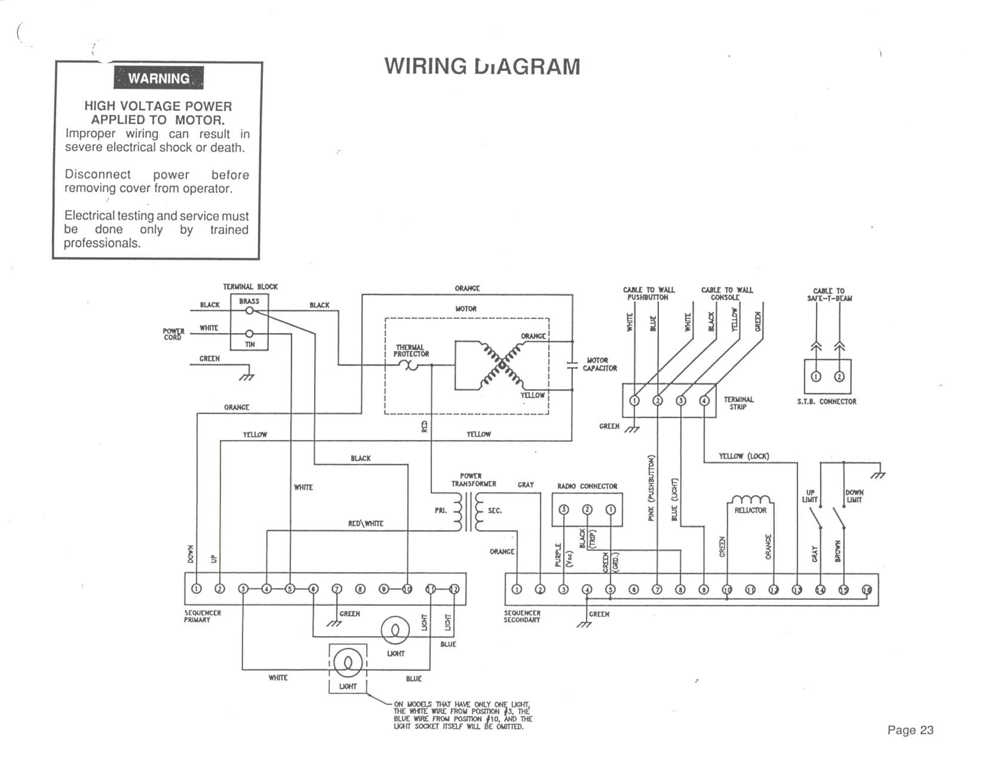
I have a Genie G-series garage door opener G5050CL
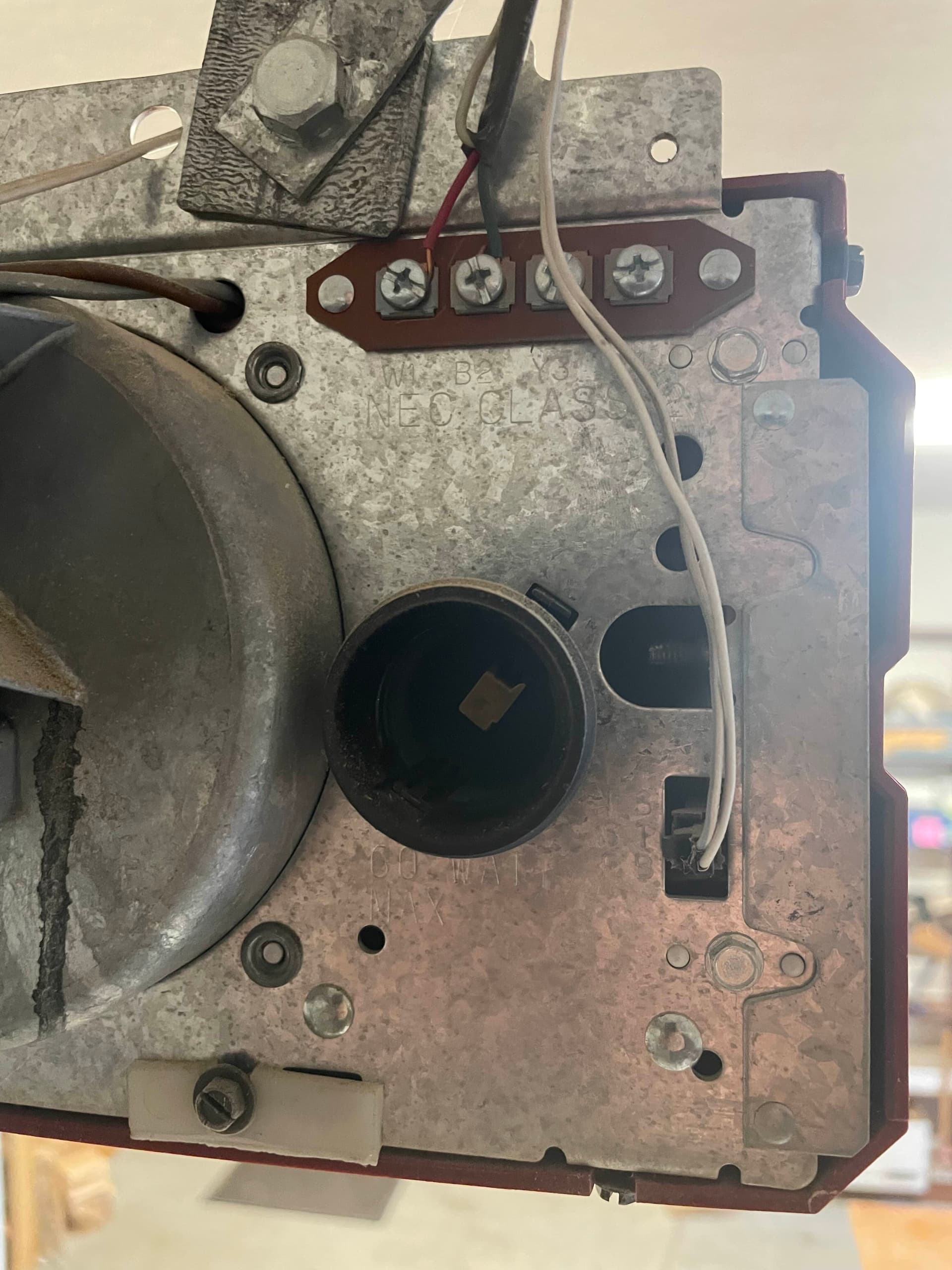
The exposed terminal are only for the “pushbutton” (we have one) and wall console (we don’t have). Terminal 1-2-3-4 and a cable that is terminated (I don’t know the name of the socket/plug - S.T.B connector?) is I guess the “obstruction sensor”, it leads to the “SAFE-T-BEAM®”.
The up and down limit are inside (those I can figure out there terminals, 14-15 and 16-green).
What I can’t figure out is where to connect the R, W and B wires. Where are the “Door opener terminals” ?
Is it the 1-2-7 (down, Up, Green)?
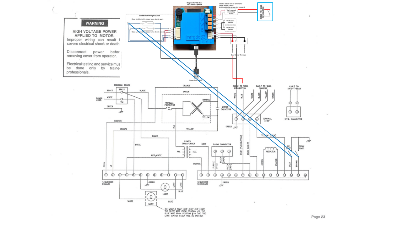
I should have studied it a bit more. All good. It works as planned.
For now I ignore the “obstruction”. May come back to it later.
So here for the “Genie 1/2 H.P. model G5050 garage door opener”.