Wow, I have to try this!
BTW, my sonoff died last week. I had added a thermometer so it may be that, but it is also possible that not cutting the transmitter and receiver lines of the dedicated en/decoder chip is a bad idea. You may want to fint them out and cut them too
Update: I reflashed it and it is fine again. Still worth cutting the transmission lines as you did.
Good to know, mine works since few days in continue but let’s make it more securely :
we replace the wires by resistors, as Tinkerman from espurna said : " resistor : anything in the range 180-680 ohms, 1/4 or 1/8 W will do. The advantage of using a resistor is that if you inadvertently solder the wrong pins, the resistor will prevent any damage to the semiconductors."
Then we isolate the en/decoder chip by cutting these lines :
The emitter at the back :
I have been watching this thread for a while and you guys are awesome! I have been able to flash tasmota, esphome, and rflink to this board because of you all. The only issue I am having is I don’t think the RF fan controller I am using is sending signals that either tasmota or esphome can understand. I can tell that it is seeing the signals being sent out but from what little I know about reading mqtt data the part that should be unique isn’t. Do you have a way to see the signals that rflink software is seeing? I can’t seem to find anything that talks about how to see this information.
Haven’t tried RFLink directly, but with esphome you can do:
# ...rest of config...
remote_receiver:
  pin: GPIO04
  dump: raw
Then connect to it with the logger. The rest of the config is here.
If your fan uses the FSK modulation and Manchester encoding, you’ll get the “shape of the pulse” as a list of pairs of numbers. Something like [+500, -100] means that the signal is high for 500 microseconds and then low for 100.
It could well be that the fan uses some other kind of modulation, in which case it may not be possible to decode with the sonoff receiver.
If you are really curious, you can get an RTL-SDR (software defined radio) dongle, they are cheap. I got one recently and I’m having a lot of fun
First off, again I have to say thank you. The ESPHome has much better documentation its just a little more manual when it comes to flashing and programing the device. Also the output is WAY more nosy, but with that said I was able to get it working with both seeing the signals and, more important for me, sending signals.
The odd thing was that all the signals looked something like this.
Your triple device is awesome
For information RFlink32 can work with ESP32 and RFM69. I use it in 868mhz and raw mode (called “debug mode” and “RFsend” in RFlink) to control my old halogen light :: the approch was similar to yours (but with only one transceiver).
Today I’ve made a little mod for the fun : I have added a serial to USB directly inside the Sonoff RF Bridge. Like this I can close the box and I have only one plug to monitor or flash it (and I don’t look for my FTDI anymore )
Soon I will update the sources of RFLink32-For-Sonoff-RF-Bridge to be able to launch the AP when the button is pressed like the re-configuration is easier.
++!
I have a V2 flashed with Tasmota that’s been working great and now need to order another one for our new vacation home. I was dismayed to read the hardware was recently changed and people couldn’t make it work anymore.
Cool! I repeated your work, everything works fine, I got the raw code. Now I would like to figure out how to make a binary sensor from this code…
And unfortunately I can’t send the code to the relay in any way. How can I check the functionality of the transmitter?
Hi Maxico, the ev1527 protocol of RFLink32 is only in reception for the moment.
To explain : RFlink32 is based on official RFlink sources which are old, very incomplete and compatible only with arduino mega. RFlink official project is not open source anymore so we have to create every protocol by our self.
So RFlink32 still in development and each developer/user can create is own protocols. For example Newkaku protocol has been added in reception and emission by coin3. Harvesting protocol has been implemented by us too on some builds (for buttons without battery). Somfy shutters protocols has been implemented too. So if we want more protocols we need more contributors to this great project
You can come to discuss with us on our RFlink discord (just here) , don’t be afraid, we discuss in french sometime but we can switch to English easily
Did you manage to flash it? I ran into the same problem, looked up the ESP chip and how to put it into flash mode (as I assumed it didn’t go into flashmode automatically). You have to connect GPI0 to ground.
I used a jumper cable, put all the wires in where they’re supposed to go except for the 3v and than connect gpio0 to ground and insert 3.3v pin. (after this you can let go of the gpio0 connection) and your Sonoff bridge should be in flash mode and you should be able to flash it.
I have a questions about your mod, as I am in the process of converting my Sonoff Bridge.
Why are the DATA+ and DATA- pins of the FTDI module (PC-side) connected to the cut D+/D- traces?
Thanks!
The FTDI is very likely tucked in and hidden inside the box. By connecting its datalines to those of the original micro usb port, he can can later flash the esp without opening the box (using the power cable).
Or is that something I will have to set up as a template myself, if that device is unknown so far?
Waiting for a I ordered SDR to be able to scan for devices better, still a bit clumsy with this RF stuff…
If you could point me to the right direction, I would be grateful.
I am in the same situation to some other here.
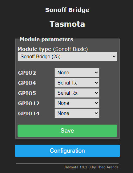
I have followed the direct hack board changes, flashed Tasmota 10.1.0.
I have configured the module type to Sonoff Bridge(25)
I have played with configuring the GPIO4 and GPIO5 pins to Serial TX/RX.
I’ve configured MQTT
But I cannot get any RF receives on the console. I think it should be automatically snooping for RF signals. I have about 3 RF remotes and none of them trigger anything. I can’t determine if I just don’t have a remote recognized by the RF chip or if the serial link to the RF chip isnt working.
I also have a broadlink 4 pro, does anyone know if there is there a Send Comand I can use from that should be observed by this RF chip?


 )
)