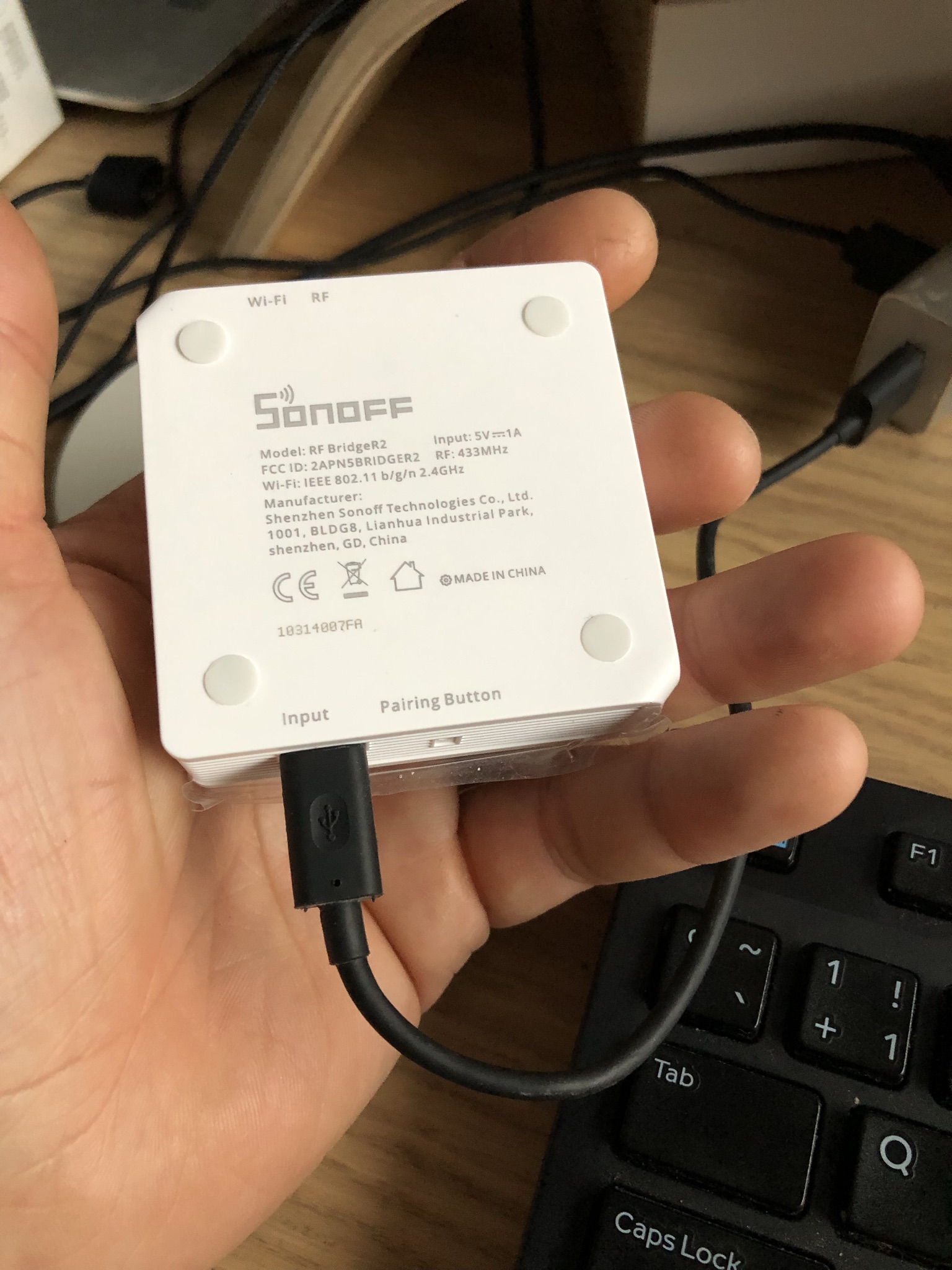
Hi everyone, I appear to have a new version of the Sonoff RF bridge board, R2 v2.2, which has a different configuration than past versions. While I was able to flash Tasmota using this guide: https://tasmota.github.io/docs/devices/Sonoff-RF-Bridge-433/
I was not able to figure out which pins to connect, or whether I need to cut any lines (I would prefer not to, but will if I have to), in order to flash Portisch.
Any help that could be provided would be greatly appreciated, and we could use any information gleaned here to update the guide for this device.
Seems like they have changed RF chips on the board. The current one has a different package than EFM8BB1. Hope the new chip will be supported otherwise it’s useless for HA…
You only need to flash portish for additional protocols that the rf bridge does not understand by itself. If all your rf433 works with the standard chip, there is no need to flash portish.
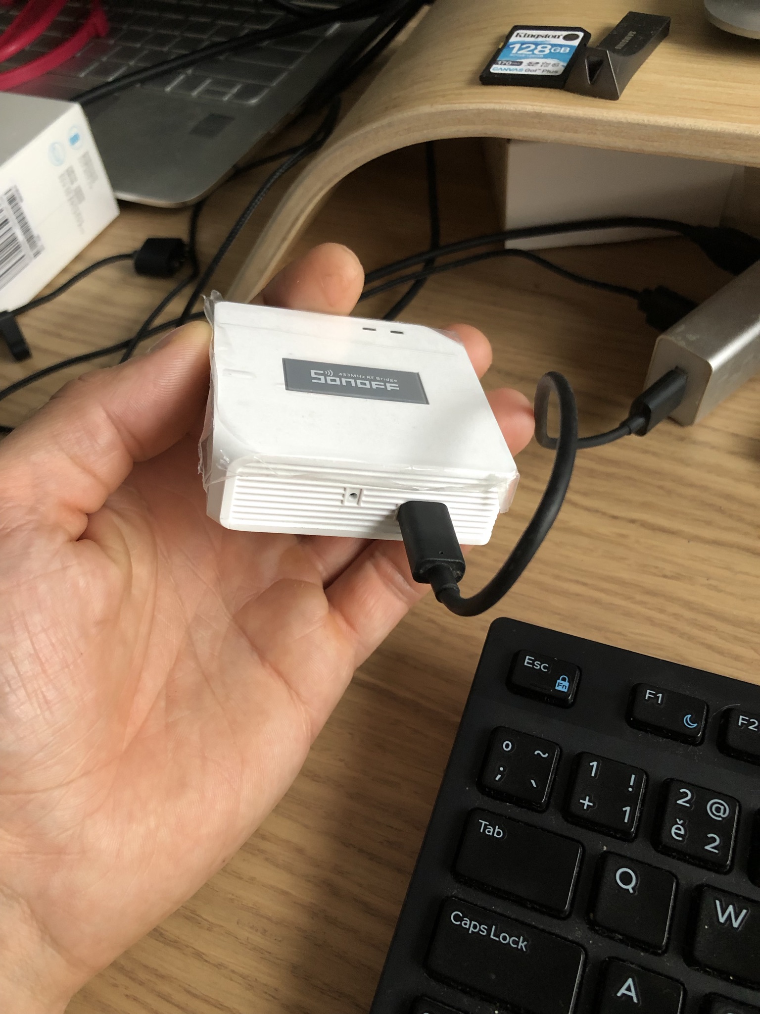
Thanks for the information, I saw the white box and wondered if it was still flashable with Tasmota.
To get the commands to show up in console for your Sonoff RF Bridge R2 v2.2, did you have to run MQTT or anything like that, or did you just open up the console and start pressing buttons on the fob? Sorry, i’m a bit of a beginner on stuff like this. I’m flashed with Tasmota, and commands are not showing up for me, but maybe there’s another step I have to take. Perhaps my device simply needs Portsich, in which case I need to go find an earlier version of the Sonoff RF Bridge, but I want to exhaust all other options first.
I did some testing and the v2.2 bridge is 1-2 seconds slower than the v2 bridge with Portisch. I use it mainly for motion triggered lights, so the delay can be annoying.
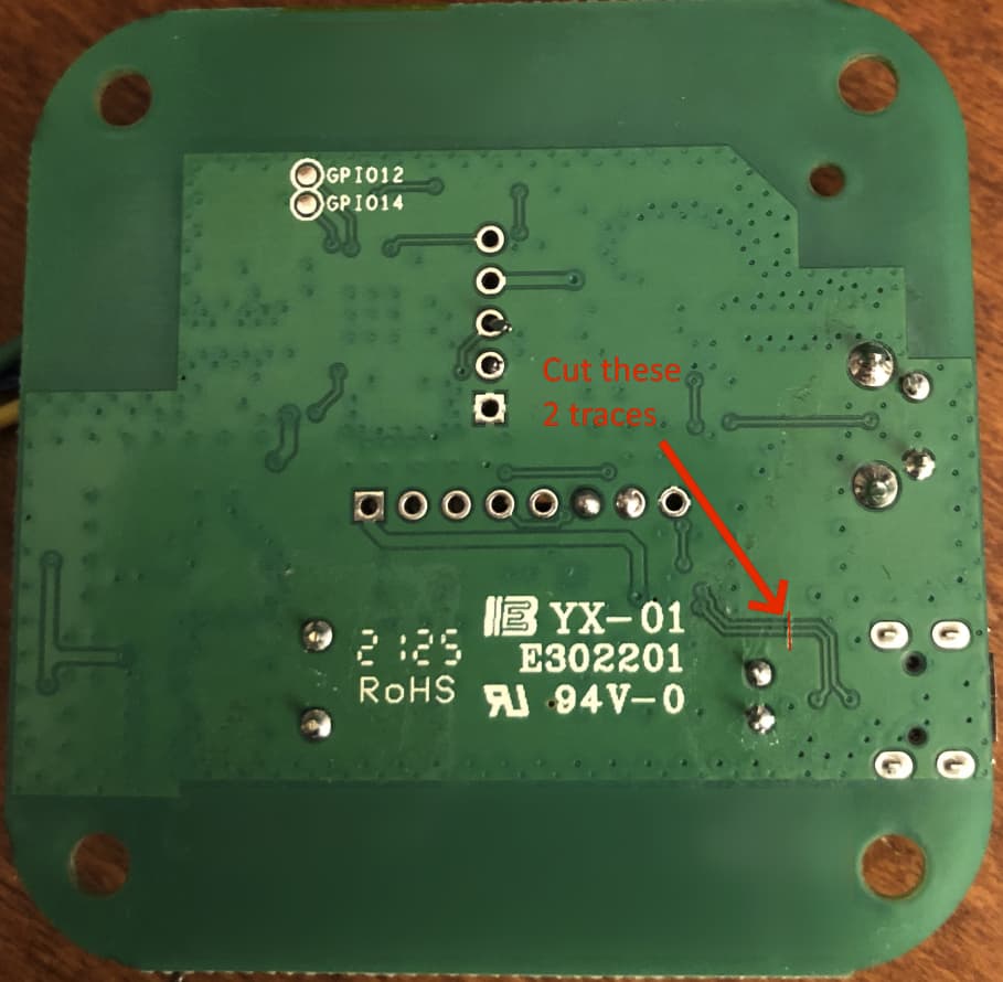
Exactly as in the original mod for older versions, these traces are connected with GPIOs we’ll use to connect the receiver and transmitter directly to the ESP8285. If left conected, usb chargers may bridge them and nothing will work (or worse).
esphome:
  name: sonoff-rf
  platform: ESP8266
  board: esp8285
  build_path: ./build/sonoff-rf

wifi:
  ssid: !secret wifi_name
  password: !secret wifi_pass
  fast_connect: true

api:
logger:
ota:
web_server:

status_led:
  pin:
    number: GPIO13
    inverted: yes

# USBRX = GPIO4 ---> receiver
# USBTX = GPIO5 ---> trasmitter

# receiver = pin 5 of the 8-legged chip (the one closer to the wifi antenna)
# transmitter = pin 4 of the 6-legged chip (closest to r12)


remote_receiver:
  pin: GPIO04
  dump: all

remote_transmitter:
  pin: GPIO05
  carrier_duty_percent: 100%

# this will log received commands, and can also transmit. Read up here:
# https://esphome.io/components/remote_transmitter.html#remote-setting-up-rf
Notes
In this mod, the existing encoder/decoder chip is not disconnected from either the transmitter nor the receiver. From what I could measure, this revision of the board has a 1k resistor between the encoder chip and the modulator, so the ESP “wins” anyway. It works perfectly fine for me, but do at your own risk. Update: The tracks to cut were found below, make sure to do that also
Hello dear team, I may need your help with a situation that I see got solved above, How did you manage to Flash tasmota on a Sonoff RF BridgeR2 – ESP8285 ( Board Version: R2 v2.2) ( Board date: 2021.01.19). After I connect the board to a windows machine and try to use this link: Install Tasmota or tasmotizer-1.2.exe I am receiving this error message: “failed to connect to esp8266 timed out waiting for packet header” I have tried pressing the “Pairing button” for 3/6/10 secconds while inserting the Prolific USB-to-Serial (Driver version: 3.3.2.120 - Date: 2008.9.24) Thank you in advance for any suggestion that you may have.
Thanks @mateine for this information !
Thanks to your help I’ve successfully flashed my R2 v2.2 with ESPhome, then I tried Tasmota and finally I build my own firmware based on RFlink32, write a documentation, made a flash script (for Windows) and posted it on github. I really recommend to try this firmware on the Sonoff RF Bridge !
There is an already compiled firmware in my github repo :
Also I propose alternative way to cut the USB data lines on the back of the board :