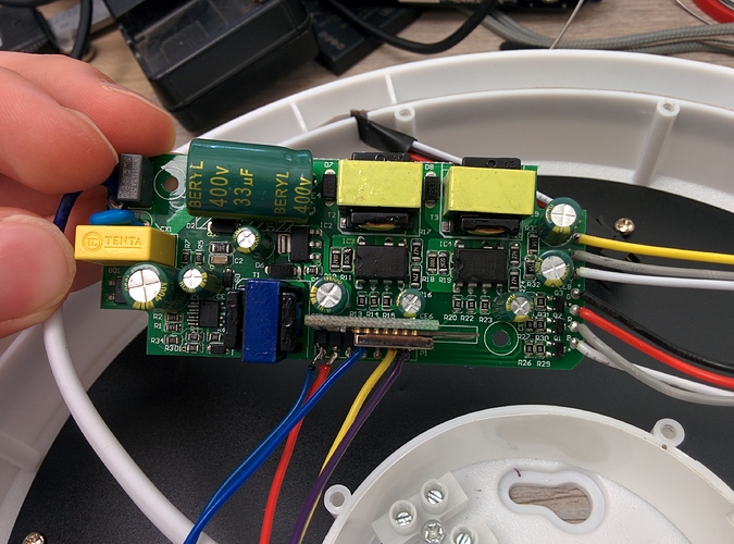
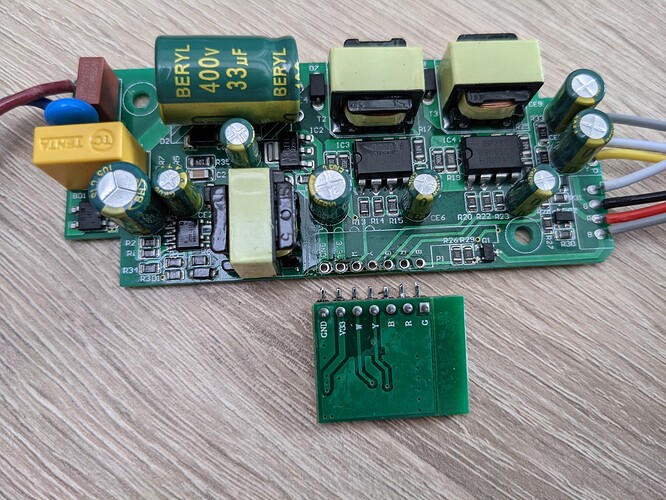
Hi, I want to share quick how to flash Tasmota firmware (or any other) to OffDarks LED lights.
EDIT: recent models might NOT have ESP and would require hardware modification and additional hardware to get Tasmota working. See the posts below!!
(60W + 36W version)
I needed some LED lights to house we are renovating. I wanted them to be some better quality ones and I found this brand - OffDarks on Aliexpress. The price looked great, reviews and photos of internals looked fine as well. They have wifi and most importantly the color temperature is configurable.
The models I have is 60W and 36W - full model name is WF-DM-60-420mm and WF-XGP-36-280mm.
Both have the same driver (which has only different current sense resistors due to different power output).
For my current use case I want to use them without any smart functions - only configure them (the color temperature) and forget. So I ordered them, plugged them into AC and…they lights up BLUE? And after a minute they are Full warm white and after another minute full cold white and blue again!
Ok so I opened the “Magic home” app, configured them to white and everything looked OK. When I flipped the regular AC switch OFF and ON again they light up in the previous white state. So far so good.
While I was playing with them I flipped the switch like three times in short timeframe. This caused them to reset to default state. I would understand this but the default state is some demo mode as I saw previously when I plugged them straight out of the box - BLUE, WARM, COLD, BLUE again! I can’t understant what kind of idiot can configure default state like this. I have Yeelight lights and their default state is neutral white. So even if you somehow reset them to default, you still have working light.
This was NOT acceptable as I can imagine that anybody can quickly flip the switch few times (anybody with kids can understand). Also the house I wanted to put them will be leased. So yeah - I can imagine the tennants will call me every time they reset the lights…
After brief look I discovered that the LED driver inside is just regular ESP8285.
(image of the driver)
So I decided to flash Tasmota firmware. I could flash ESPhome but currently I plan to use those lights in offline mode and the tasmota has nice web interface so I can easily configure it after I start wifi hotspot on my mobile phone.
Quick tutorial on how to flash:
- Disconnect AC 230V line from the light - power to the chip will be provided from the USB-serial converter. Don’t risk flashing it while powered on from AC!
- Disassemble the light
- Connect (solder) wires to Tx, Rx, GPIO0, power and ground
- Connect it with USB-serial converter* or as I used regular ESP8266 development board (nodemcu). I just pulled ENable to ground on this board so the ESP8266 does not interfere with the flashing. In this case you connect RX to RX and TX to TX. And not as you are used to (TX to RX and RX to TX)
- Connect GPIO0 to GND (flashing mode)
- Download binary of Tasmota and flasher (tasmotizer).
- Connect USB-serial converter to PC
- Open tasmotizer, choose the binary file, COM port and Flash it
- Desolder everything, assemble the light and power on.
- Use mobile phone (or anything with wifi) to connect to newly created wifi AP (tasmota_…)
- Open 192.168.4.1 and configure your home AP’s name and key to connect
- Configue->configure other and paste this template:
{"NAME":"Offdarks","GPIO":[0,0,0,0,0,0,0,0,37,38,0,0,0],"FLAG":0,"BASE":18} - Check activate and Save
*If you are using some USB-serial adapoter be careful if the converter uses only 3.3V on RX/TX lines. And second warning - you need stable 3.3V with high current capability - not all USB-serial converters can deliver enough current to power the chip! That is why I used Nodemcu board
Other useful settings I configured:
Click “console” and paste folowing commands.
As I will use it in offline mode I sent following commands:
Disable MQTT:
SetOption3 0
Display hostname and IP address in GUI:
SetOption53 1
And most importantly: Device recovery using fast power cycle detection DISABLE!!!
SetOption65 1
This means that nobody can reset this light by fast switching the wall switch.
After this firmware update I am 100% satisifed with those lights. 
As I mentioned earlier if I start wifi network with the correct name, all light will connect and I can configure them using web browser. Here is image of how it looks - the top slider controls light temperature, the bottom one controls the brightness
Those lights have RGB strip at the top but in my use case it makes no sense to use it so I didn’t implement it into the tasmota firmware. But it can be of course added later.
The RGB configuration is following
GPIO14=blue
GPIO4=green
GPIO5=red
EDIT: so I implemented the RGB:
Just use the template
{"NAME":"Offdarks_RGB","GPIO":[255,255,255,255,38,37,255,255,40,41,39,255,255],"FLAG":0,"BASE":18}
By default you can use RGB OR White. If you want to have RGB independent on White (so you can have white light + RGB on top of that) you must input to console following:
SetOption37 128
Another setting I used - to set default state and NOT store any changes made during use:
First set the configuration you want (brightness, RGB color etc)
Hit restart and make sure it went back to what you want it
Then set following:
SaveData 0 (this stops saving changes made to internal flash)


 but just look at the driver board’s markings and ignore the small board.

