So this thread was about creating an open source wifi module for Gree based air conditioners/heatpumps like Sinclair, Daizuki, TGM etc etc.
It turned out that github user piotrva already had this working: GitHub - piotrva/esphome_gree_ac His code had some problems though. I fixed those. I also added a ‘silent mode’ switch so that you can stop the AC from beeping when changing the settings via wifi.
Here’s my github with instructions on how to get this up and running. If there are any questions just let me know!
Haven’t connected either just yet, problem is that the airco hangs 2m high on a wall, but I guess I can connect the UART to a small PC, attach it to the airco and then use it via a remote desktop to manage the connection. So will be trying that soon.
The firmwares for this particular module can be found here: gree-wifimodule-firmware/362001065279 at main · maxim-smirnov/gree-wifimodule-firmware · GitHub
You can load them up in Ghidra using Cortex little Endian. However I havent figured out the firmware layout just yet, most of the FW disassembles but there seem to be at least 3 different partitions in the FW. (bootloader, main code and data it seems. It seems at 0x200 the first partition start with the first 4 bytes being the partition length, so you can work from there to find the other partitions). Also haven’t figured out the loading addresses just yet. Not sure if it’s all even needed, probably better to first connect the UART and start sniffing packets, hopefully that already would be enough to get a good idea of the protocol used in this particular module, together with the existing code that Piotr already developed that might already be enough.
Ok I managed to parse the OTA firmwares. I found this great tool that works very well:
The sections I already had identified (as mentioned above) but this tool also shows the loading address:
section 1: Bootloader @0x10000480
section 2:FW code @0x9b000140
section 3: data @0x9b800140
(all for that v1.26 FW dump I mentioned earlier)
So I now loaded the section 2 and 3 to the correct address in Ghidra and now everything decompiles correctly. So the reverse engineering of the firmware can now really start
Not sure if this is even necessary but as the guy(s) who analyzed the sniffed frames had still some doubts as to what is what, it can now be analyzed via the firmware code.
So as noted by “bekmansurov” on his github page, packages always start with:
0x7E, 0x7E
And then the following byte is the package length. However he identifies that byte as ‘command byte’ too, he writes “Usually packets have different length byte so it’s convenient to use this byte as a packet identifier.” However it seems that actually the following byte is the command byte (so the identifier) !! (at least for the out going packets, haven’t checked the incoming ones yet)
So for example, a package that he identifies as a ‘0x10’ packet:
10 02 00 00 00 00 00 00 01 00 28 1e 19 23 23 00 b8
This should actually be identified as a ‘02’ packet, which is the ‘command’ (or identifier) of the packet! So the command 0x2 packet has length 0x10.
Or in other words, the first 4 bytes of each packet are: 0x7E, 0x7E, [length], [CMD]
So that’s of course super important to realize. In fact I see different packet lengths in the firmware code than bekmansurov noted, but for the same commands.
So far I have identified 5 different outgoing packet types (so from WIFI module to the AC) :
CMD 0x01. Length 0x2F in my firmware.
CMD 0x02. Length 0x10 in my firmware.
CMD 0x03. Length 0x1A in my firmware.
CMD 0x04. Length 0xD in my firmware.
CMD 0x0D. Length 0x7 in my firmware.
At this point I’m pretty sure that’s all there is, but if I find more I will update here. I still need to identify what these exactly do. “bekmansurov” had identified 0x2 as the first command to the AC after the wifi module powers up. And Command 0x1 as the packets conveying the commands to the AC. And he couldn’t find out what the others were. Will look into all that …
Anyway it’s interesting to see that the commands actually have different lengths than “bekmansurov” found.
Actually I think his code works on most gree models. I thought it wouldn’t because some guy commented on his github that it didn’t work but I now think that guy did something wrong.
Going to order the parts myself and try it!
I do see he didn’t find command 0xD though. I think this might be a secret debug code that puts the air conditioner in a special factory mode, I saw several references to such mode in the firmware. Will investigate all that
The other commands he noted are commands from ac to the module, haven’t really looked into that yet but I saw similar commands indeed. Will also look into that. But it actually seems his code should be working universally for gree branded acs
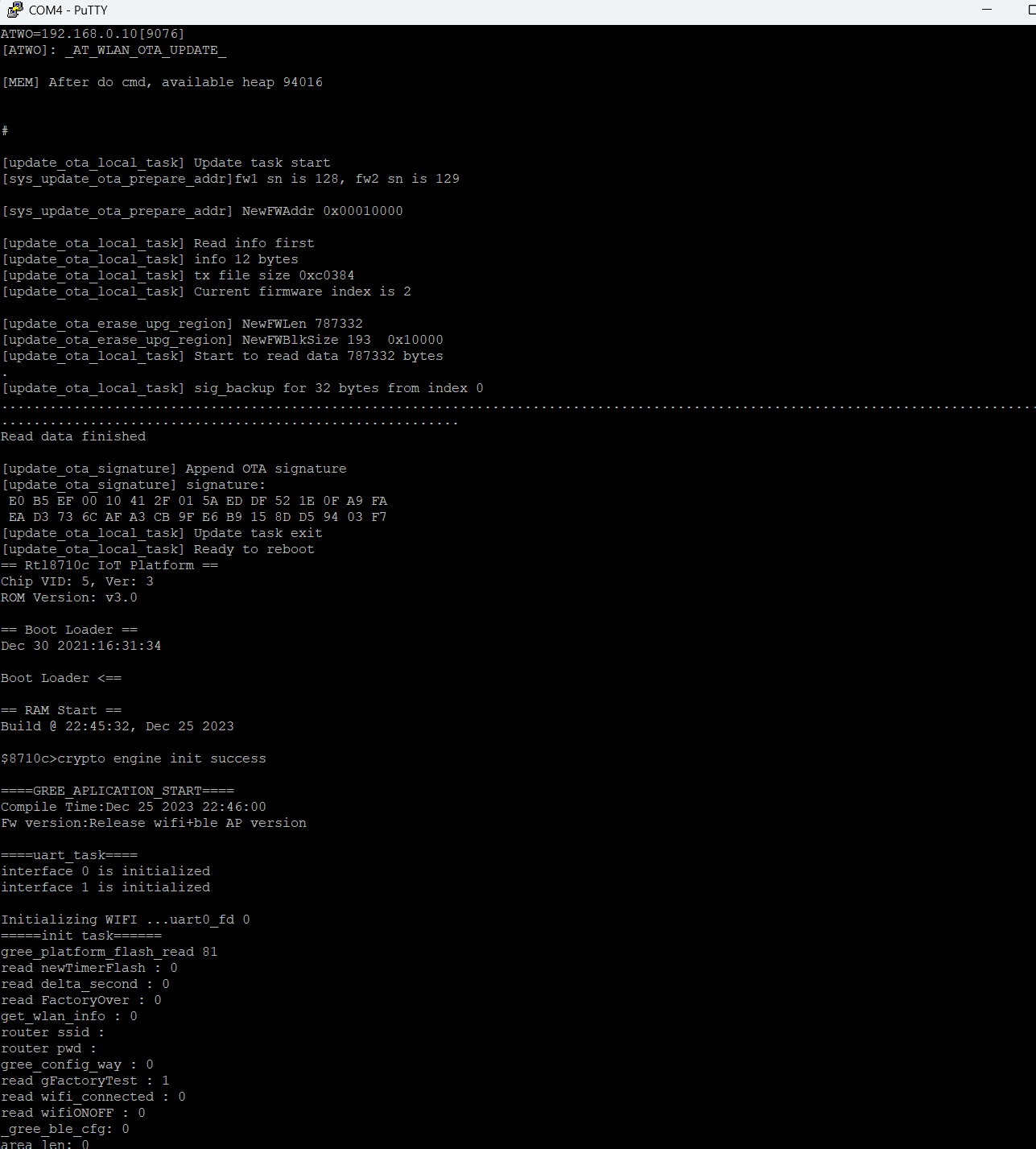
Once connected to the debug UART you can issue these GREE specific commands:
[GATF]: Enter Factory Test Mode
[GATR]: Gree Reset
[ATST]: Gree Reboot
[GATO]: Gree Enter OTA Upgrade
Anyway, I used up pretty much all of my free time for the coming few weeks, LOL, so going to work on some other stuff now. I’ve ordered the components to build the ESP32 unit like described in “Piotrva”'s github post from my first post. His code should definitely work for most GREE branded models as the protocol he uses matched the one I’ve been reverse engineering, the GRJWB04-J, which seems to work in a lot of GREE branded models.
So in a few weeks I’ll try that. I read on his github page that the AC doesn’t seem to always process the commands, sometimes it ‘misses’ one, if that indeed happens I’ll look into that and see if there’s a way to fix that. It could be for example that we’ll need to better mimic the original communication since it seems he only sends the 0x1 command. Could be that we’ll need to implement the others too …
BTW if anyone is interested in playing with the above commands, be careful! I managed to brick my module, not even sure how I did it, LOL, but it didn’t boot correctly anymore, it wouldn’t start the bluetooth access point anymore (and I hadnt configured wifi yet on this module). Also it wouldnt even issue packets to the AC anymore … Maybe it was because I tried the ‘factory mode’ command, not sure… Anyway, luckily I could still issue commands via the debug UART. With the “ATWC” command I could have the module join my home wifi. With the ‘downloadserver’ tool (ambd_sdk/tools/DownloadServer at dev · ambiot/ambd_sdk · GitHub) I could create a local server with the new firmware. Then with the ATW0 command I could flash the FW. I took the opportunity to upgrade to the latest v1.53 FW (downloaded from that github page in my first post) and everything works again
Ok I finally had some time to mess around with this again. I had actually ordered both an ESP01 as an ESP32 to test it with. But since I had just flashed an ESP01 with the Midea firmware (for another AC) I thought I’d try it again with an ESP01 and it worked! Well 99% It does communicate with the AC but among correct packets I saw a fan mode error. Will look into that, doesn’t seem to be a biggy. But I can change temperature, turn it on/off etc, so seems to work mostly fine! I do find that it occassionally doesn’t seem to process a settings change, something that the author of all this also saw, but will need to look into that.
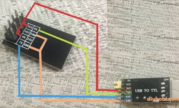
How I did it: I bought this: https://nl.aliexpress.com/item/1005008528226032.html
So that’s both an ESP01 and the ‘adaptor’ board for 3.3V ↔ 5V conversion (since the ESP01 uses 3.3V and the AC uses 5V). Then I created a new project in the HA Esphome builder based on ESP01. Then I modded the below YAML with the keys and passwords from the default generated yaml:
substitutions:
  node_name: gree # Use a unique name.
  node_id: Gree_ac    # Use a unique id.
  friendly_node_name: "Gree AC"
  deviceid: gree
  devicename: AC Bedroom

esphome:
  name: gree
  friendly_name: "Gree AC"

esp8266:
  board: esp01_1m

# Enable Home Assistant API
api:
  encryption:
    key: [insert yours here]

ota:
  - platform: esphome
    password: [insert yours here]

wifi:
  ssid: !secret wifi_ssid
  password: !secret wifi_password

  # Enable fallback hotspot (captive portal) in case wifi connection fails
  ap:
    ssid: "Gree Fallback Hotspot"
    password: [insert yours here]

captive_portal:

# Enable logging
logger:
  baud_rate: 0 # disable LOG output on UART as UART is used for Sinclair AC unit
  #level: VERBOSE

uart:
  tx_pin: 1
  rx_pin: 3
  baud_rate: 4800
  parity: EVEN

time:
  - platform: sntp

external_components:
  - source: github://piotrva/esphome_gree_ac
    components: [sinclair_ac]
    refresh: 0s

climate:
  - platform: sinclair_ac
    name: ${devicename}
    horizontal_swing_select:
      name: ${devicename} Horizontal Swing Mode
    vertical_swing_select:
      name: ${devicename} Vertical Swing Mode
    display_select:
      name: ${devicename} Display Mode
    display_unit_select:
      name: ${devicename} Display Unit
    plasma_switch:
      name: ${devicename} Plasma
    sleep_switch:
      name: ${devicename} Sleep
    xfan_switch:
      name: ${devicename} X-fan
    save_switch:
      name: ${devicename} Save/8 Heat
About the “unknown fan mode” problem, I see in the logs that my fan mode is 0x91, that other guy who did also a protocol description actually found this mode:
##### Byte 8 (MODE + FAN)

0x10 - set AC to turn OFF

0x80 - AUTO MODE (0x80 - auto FAN SPEED, 0x81 - low, 0x82 - medium, 0x83 - high)

0x90 - COOL MODE (0x90 - auto FAN SPEED, **0x91** - low, 0x92 - medium, 0x93 - high)

0x98 - ?

0xA1 - DRY MODE (only low FAN SPEED, no other settings are available in my AC)

0xB0 - FAN ONLY MODE (0xB0 - auto FAN SPEED, 0xB1 - low, 0xB2 - medium, 0xB3 - high)

0xC0 - HEAT MODE (0xC0 - auto FAN SPEED, 0xC1 - low, 0xC2 - medium, 0xC3 - high)

0x01 - ?

0x21 - ?
So would need to change the code to incorporate that. Small fix.
So the main ‘bug’ still is that the AC seems to drop some of the commands. I’m pretty sure I’m onto this, I’ve documented this in the thread on the github of piotvra, who wrote the code: Command sometimes is rejected · Issue #2 · piotrva/esphome_gree_ac · GitHub
Like I stated there, I now need to implement that but I’ve spent the whole weekend on this already and ran out of free time, will be a while before I can work on this …
Hello I’m new to gree-based AC users party, so excuse me if the question is answered somewhere already.
What is the main benefit comparing to manufacturer’s wifi? I’ve seen Gree integration (although not tested it yet), expecting it works with original wifi.
If you have an original module, I guess the difference would be mostly security, it’s always preferable to not have your machines communicate with an external (Chinese) company. Others could also exploit it, depending on the security setup of your network. But the biggest advantage is for people who don’t have a module yet and need to buy one. The ESP01 literaly costs only 2 dollars while these modules on aliexpress sell for around $30.
Another advantage though is that you don’t need your wifi module to have a fixed ip. In the Gree implementation for the original module you need to assign a static IP in your router to the module’s MAC address. Not all routers support this. With this open source ESP module that’s not needed, everything works automatically.