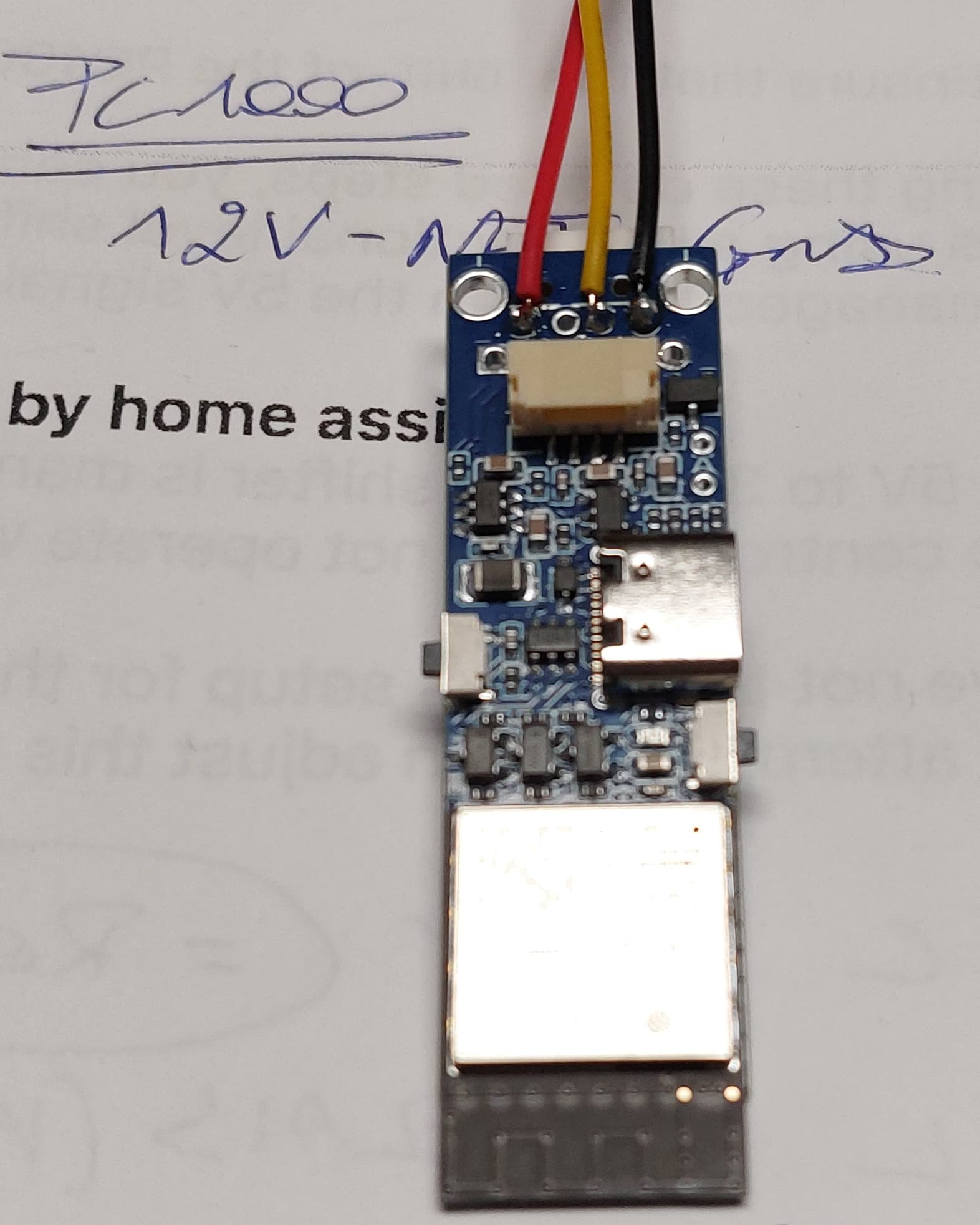
For anyone interested, my summer project was to create a fully functional esphome component for the PC1001 and you can find the project here:
GitHub - sle118/hayward_pool_heater.
This is based on the initial work of njanik, who decyphered the bus layer protocol and timings, opening the door to analyzing the data itself.
Here’s the result so far:


I did stumble on this very informative technical manual which provides a lot of details on all the heat pump parameters (the same type of document was also available on this forum for the PC1002, which uses the RS485 protocol).
So with this available, I needed a simple way to capture changes in packet data when performing configuration changes on the heat pump controller. This was done with some highlighting of “changed” packets, in which changed bytes and elements are also highlighted. An example of this shows a coil temperature change
To streamline the analysis process, I also needed a simple way to extract relevant log lines and tag them for the following scenario:
- Logging specific changes made from the factory settings, where I am expecting a message to be sent by the keypad controller to the heat pump to capture the values needed to change various parameters
- Logging state changes from the heat pump itself when, for example, I turn off the pool’s water pump which results in a S02 water flow condition switch to be raised, indicating that the water stopped flowing
- Searching for temperature data in packets for t0* (temperature condition) values. These can be observed from the factory menu and searching allows correlating packet data with the value seen on the controller
- Searching for decimal values. Similar to the previous search capability, but for non-temperature values which are encoded differently in packet data.
And so the logs annotator was born. Here it is in action, logging a temperature change from the controller

and the resulting output
Usage:
python analysis\hwp_logs_annotator.py --help
usage: hwp_logs_annotator.py [-h] --yaml YAML [--device DEVICE] [--log_prefix LOG_PREFIX] [--delay DELAY]

Run ESPHome logs with daily log rotation, manual tagging, and filtering.

options:
  -h, --help            show this help message and exit
  --yaml YAML           YAML configuration file for ESPHome.
  --device DEVICE       Device IP address for ESPHome logs.
  --log_prefix LOG_PREFIX
                        Path and prefix for the log files. Example: /path/to/logs/my_log_prefix
  --delay DELAY         Reaction delay in seconds. Default is 1.5
You can let the tool run to capture logs and they will be written to a log file (with a prefix of your choice). The delay option is used to default the values in “duration” fields.
There are many fields that are not yet covered, but so far, the following will be reported to home assistant (excuse the c++ code, but I put all the details in that documentation and so I think it’s fairly readable for non technical people):
typedef struct {
    /// @brief optional time_t value
    /// This is the heat pump's clock value. The clock is typically used by the heat pump for
    /// operating modes which depend on the time, for example fan mode time.
    /// @see FanMode
    optional<std::time_t> time;

    /// @brief Heating mode restrictions
    /// This is the heat pump's heating mode restrictions. It can be cooling only, heating only, or
    /// no restrictions.
    /// @see HeatPumpRestrict
    optional<HeatPumpRestrict> mode_restrictions;

    /// @brief Fan mode
    /// This is the heat pump's fan mode.
    /// @see FanMode
    optional<FanMode> fan_mode;

    /// @brief Climate action
    /// This is the current activity being performed by the heat pump
    /// @see climate::ClimateAction
    optional<climate::ClimateAction> action;

    /// @brief Climate mode that is requested from the heat pump
    /// @see climate::ClimateMode
    optional<climate::ClimateMode> mode;

    /// @brief Start defrost temperature in degrees Celsius.
    /// Represents the temperature threshold at which the heat pump initiates the defrost cycle.
    /// The condition must be sustained for the time specified in
    /// `d03_defrosting_cycle_time_minutes` before the defrost cycle begins.
    optional<float> d01_defrost_start;

    /// @brief End defrost temperature in degrees Celsius.
    /// Establishes the temperature threshold above which the defrost cycle ends,
    /// allowing the system to return to normal heating mode.
    optional<float> d02_defrost_end;

    /// @brief Defrost cycle time in minutes.
    /// Represents the required delay (in minutes) between two successive defrost cycles.
    /// For the first defrost initiation, the coil temperature must remain below `d01_defrost_start`
    /// for the entire duration of `d03_defrosting_cycle_time_minutes`.
    optional<float> d03_defrosting_cycle_time_minutes;

    /// @brief Maximum defrost duration in minutes.
    /// Represents the maximum allowable duration for a single defrost cycle. The defrost cycle
    /// will end when this time is reached, even if the temperature threshold (`d02_defrost_end`)
    /// has not been met.
    ///
    /// Special scenarios for abnormal defrost termination:
    /// 1) If the unit is shut off during defrosting, the system will complete the defrost cycle
    /// before stopping.
    ///
    /// 2) If the high-pressure (HP) switch malfunctions during defrost, the unit
    /// will shut down and indicate an HP malfunction. Upon recovery, the system will return to
    /// normal heating mode.
    ///
    /// 3) If the low-pressure (LP) switch malfunctions, the unit skips the LP fault and continues
    /// defrosting. After defrosting completes and normal heating resumes, the LP switch will be
    /// re-checked after 5 minutes.
    ///
    /// 4) If the flow switch malfunctions, the unit will shut off and indicate a Flow malfunction.
    /// After recovering, the system will continue defrosting until `d04_max_defrost_time_minutes`
    /// elapses.
    ///
    /// 5) If the exhaust temperature is too high, the unit will shut down to indicate the issue.
    /// After recovery, defrosting resumes until the maximum defrost time (`d04`) is reached.
    ///
    /// 6) If the temperature difference between inlet and outlet is too high during defrosting,
    /// the unit will shut down and show a malfunction. Once recovered, the system will continue
    /// defrosting until the maximum defrost time is reached.
    ///
    /// 7) If antifreeze protection is triggered during defrosting, the unit will shut down and show
    /// a malfunction. After recovery, defrosting will continue until the maximum defrost time
    /// (`d04`) is reached.
    optional<float> d04_max_defrost_time_minutes;

    /// @brief Minimum defrost time in minutes in economy mode.
    /// Defines the minimum duration for the defrost cycle when operating in defrost economy mode,
    /// ensuring the defrost cycle achieves effective operation under energy-saving constraints.
    /// @see DefrostEcoMode
    optional<float> d05_min_economy_defrost_time_minutes;

    /// @brief Defrost economy mode.
    /// Configures the heat pump's economy mode for defrosting, allowing for reduced energy usage
    /// when certain operational thresholds are met, typically extending the defrost cycle under
    /// less demanding conditions.
    /// @see DefrostEcoMode
    optional<DefrostEcoMode> d06_defrost_eco_mode;

    /// @brief Suction temperature in degrees Celsius.
    /// Represents the temperature of the refrigerant entering the compressor, aiding in assessing
    /// cooling performance.
    /// @todo suction temperature position in the buffer has to be determined
    optional<float> t01_temperature_suction;

    /// @brief Inlet water temperature in degrees Celsius.
    /// Measures the temperature of the water entering the heat pump, determining the heating
    /// demand.
    optional<float> t02_temperature_inlet;

    /// @brief Outlet water temperature in degrees Celsius.
    /// Measures the temperature of the water exiting the heat pump, reflecting heat transfer
    /// effectiveness.
    /// @todo outlet temperature position in the buffer has to be determined
    optional<float> t03_temperature_outlet;

    /// @brief Coil temperature in degrees Celsius.
    /// Indicates the temperature of the evaporator or condenser coil, helping assess the efficiency
    /// of heat transfer.
    optional<float> t04_temperature_coil;

    /// @brief Ambient temperature in degrees Celsius.
    /// Reflects the external air temperature around the heat pump, impacting efficiency and
    /// operational adjustments.
    /// @todo ambient temperature position in the buffer needs to be confirmed
    optional<float> t05_temperature_ambient;

    /// @brief Exhaust temperature in degrees Celsius.
    /// Represents the temperature of the refrigerant or air exiting the compressor or heat
    /// exchanger, indicating heat pump output performance.
    optional<float> t06_temperature_exhaust;

    /// @brief Water flow meter status. If true, the flow meter is enabled and the heat pump can
    /// operate.
    /// @see FlowMeterEnable
    optional<FlowMeterEnable> S02_water_flow;

    /// @brief Target temperature in degrees Celsius. This is the desired temperature that the heat
    /// pump should maintain.
    optional<float> target_temperature;

    /// @brief Minimum target temperature in degrees Celsius. This is the lowest temperature that
    /// the heat pump can maintain in cooling mode.
    optional<float> min_target_temperature;

    /// @brief Maximum target temperature in degrees Celsius. This is the highest temperature that
    /// the heat pump can maintain in heating mode.
    optional<float> max_target_temperature;

    /// @brief Cooling setpoint temperature in degrees Celsius. This is the temperature at which the
    /// heat pump starts cooling.
    optional<float> r01_setpoint_cooling;

    /// @brief Heating setpoint temperature in degrees Celsius. This is the temperature at which the
    /// heat pump starts heating.
    optional<float> r02_setpoint_heating;

    /// @brief Auto mode setpoint in degrees Celsius. This is the temperature at which the heat pump
    /// operates in auto mode.
    optional<float> r03_setpoint_auto;

    /// @brief Temperature difference to maintain during cooling operation in degrees Celsius.
    /// This value represents the temperature difference between the setpoint and the actual water
    /// temperature that the heat pump strives to maintain while cooling. It's used to ensure
    /// efficient cooling performance.
    optional<float> r04_return_diff_cooling;

    /// @brief Temperature difference that triggers shutdown when cooling in degrees Celsius.
    /// This value defines the temperature difference threshold that, when exceeded, causes the heat
    /// pump to shut down the cooling operation to prevent overcooling. It's a safety feature to
    /// protect the system and maintain desired conditions.
    optional<float> r05_shutdown_temp_diff_when_cooling;

    /// @brief Temperature difference to maintain during heating operation in degrees Celsius.
    /// This value represents the temperature difference between the setpoint and the actual water
    /// temperature that the heat pump strives to maintain while heating. It's used to ensure
    /// efficient heating performance.
    optional<float> r06_return_diff_heating;

    /// @brief Temperature difference that triggers shutdown when heating in degrees Celsius.
    /// This value defines the temperature difference threshold that, when exceeded, causes the heat
    /// pump to shut down the heating operation to prevent overheating. It's a safety feature to
    /// protect the system and maintain desired conditions.
    optional<float> r07_shutdown_diff_heating;

    /// @brief Minimum cooling setpoint in degrees Celsius. This is the lowest temperature that the
    /// heat pump can maintain in cooling mode.
    optional<float> r08_min_cool_setpoint;

    /// @brief Maximum cooling setpoint in degrees Celsius. This is the highest temperature that the
    /// heat pump can maintain in cooling mode.
    optional<float> r09_max_cooling_setpoint;

    /// @brief Minimum heating setpoint in degrees Celsius. This is the lowest temperature that the
    /// heat pump can maintain in heating mode.
    optional<float> r10_min_heating_setpoint;

    /// @brief Maximum heating setpoint in degrees Celsius. This is the highest temperature that the
    /// heat pump can maintain in heating mode.
    optional<float> r11_max_heating_setpoint;

    /// @brief Last heater frame
    optional<uint32_t> last_heater_frame;

    /// @brief Last controller frame
    optional<uint32_t> last_controller_frame;

    /// @brief Indicates if a Flow Meter is installed and enabled
    /// @see FlowMeterEnable
    optional<FlowMeterEnable> U01_flow_meter;

    /// @brief Flow meter pulses per liter
    /// @see FlowMeterEnable
    optional<float> U02_pulses_per_liter;

    /**
     * @brief Determines if a given temperature is within the valid range
     *
     * The valid range is determined by the heat pump's operating mode
     *
     * @see esphome::climate::ClimateMode
     * @param temp  Temperature in degrees Celsius
     * @return true
     * @return false
     */
    bool is_temperature_valid(float temp) const {
        return temp >= this->get_min_target() && temp <= this->get_max_target();
    }

    /**
     * @brief Get the min target value in degrees Celsius
     *
     * The min value is determined by the heat pump's operating mode, each of which
     * having a different min value
     *
     * @see esphome::climate::ClimateMode
     *
     * @return float
     */
    float get_min_target() const { return this->min_target_temperature.value_or(15); }

    /**
     * @brief Get the max target value in degrees Celsius
     *
     * The max value is determined by the heat pump's operating mode, each of which
     * having a different max value
     *
     * @see esphome::climate::ClimateMode
     *
     * @return float
     */
    float get_max_target() const { return this->max_target_temperature.value_or(33); }
} heat_pump_data_t;
Using it yourself is as simple as ading this to your esphome yaml:
external_components:
  - source: github://sle118/hayward_pool_heater
    components: hwp
and then adding the climate component:
climate:
  - platform: hwp
    id: pool_heater
    name: "Pool Heater"
    pin_txrx: ${CLIMATE_TXRX_PIN}
if you want to use the log annotator (and possibly contribute), you should enable more verbose logging. Here is what I use
logger:
  level: VERBOSE
  tx_buffer_size: 2048

  logs:
    esp-idf: INFO
    hwp: VERBOSE
    hwp.pk: VERBOSE
    sensor.filter: INFO
    api: INFO
    api.service: INFO
    api.connection: INFO
    api.socket: INFO
    scheduler: INFO
    component: ERROR
    mdns: INFO
    adc: INFO
    climate: INFO
    text_sensor: INFO
    select: INFO
    number: INFO
    sensor: INFO
    esp32.preferences: INFO
    wifi: INFO
Hoping this will help someone, but on top of it all, hoping this will motivate someone to step in and help with the protocol analysis or better, help with the code.
I’ve tried my best to also keep the code well documented and to use a design that hopefully would allow someone to leverage the code for controllers which have the same bus packet structure but a slightly different protocol. Since packet decoding is done via dependency injection (if you know, you know… if you don’t, have a look at the code), it’s relatively easy to implement new decoders with little code and little “touching” of the core implementation.