Problem visualizing percentage of actual voltage on pin

Hi everyone. I’m new in the esp32-world, and I have a probably “noob-question”.
I build a device that should control a ventilation speed by potentiometer (it uses a voltage from 0 to 5v DC for set a motor freequency). So I got in my setup a esp32, motorized potentiometer (ALPS), 2-relay module (for controling the potentiometer’s motor direction) and 1306 OLED display for visulaize actual voltage in percent (0% = 0V DC… 100% = 5V DC). So the problem I have is the sensor (+ display) that shows a huge range of percentage, like from -3% to 146%… And I’m not able to calibrate it properly, even with 10 decimals, every time getting -3 - 1(46)% or smaller range, like 15-95%… the pin used as sensor is connected with resistor, so real voltage that comes to it is about 0.1V DC to 2,5V DC. Here is the script I’m using:

esphome:
  name: espex
  friendly_name: espex

esp32:
  board: esp32dev
  framework:
    type: arduino

# Enable logging
#logger:

# Enable Home Assistant API
api:
  encryption:
    key: "key"

ota:
  - platform: esphome
    password: "blabla"

wifi:
  ssid: !secret wifi_ssid
  password: !secret wifi_password

  # Enable fallback hotspot (captive portal) in case wifi connection fails
  ap:
    ssid: "Esph2"
    password: "blabla"

captive_portal:
    
sensor:
  - platform: adc
    pin: 34
    name: "pot_position"
    id: pot_position
    accuracy_decimals: 0
    update_interval: 200ms
    raw: True
    device_class: voltage
    attenuation: 12dB
    samples: 99
    unit_of_measurement: “%”
    filters:
      - multiply: 0.00095238
      - calibrate_linear:
          - 0.00000000 -> 0.00
          - 1.25000005 -> 50.00
          - 3.89995555 -> 100.00
  - platform: template
    id: pot_raw
    name: "pot_raw"
    lambda: return id(pot_position).state;


switch:
  - platform: gpio
    pin: 25
    name: "Relay #1"
    id: relay1
    icon: mdi:fan-minus
    on_turn_on: 
      then:
        - display.page.show: page2
        - component.update: oleg
        - switch.turn_on: relay1
        - delay: 50ms
        - switch.turn_off: relay1
        - display.page.show: page1
        - component.update: oleg 
    interlock: [relay2]

  - platform: gpio
    pin: 26
    name: "Relay #2"
    id: relay2
    icon: mdi:fan-plus
    on_turn_on: 
      then:
        - display.page.show: page2
        - component.update: oleg
        - switch.turn_on: relay2
        - delay: 500ms
        - switch.turn_off: relay2 
        - display.page.show: page1
        - component.update: oleg 
    interlock: [relay1]


font:
  - file: "fonts/Roboto-Regular.ttf"
    id: font_small
    size: 12
  - file: "fonts/Arial.ttf"
    id: font_large
    size: 32
  - file: "fonts/Arial.ttf"
    id: font_mid
    size: 22

i2c:
  sda: 33
  scl: 32
  scan: true

display:
  - platform: ssd1306_i2c
    model: "SSD1306 128x64"
    address: 0x3C
    update_interval: 200ms
    id: oleg
    pages:
      - id: page1
        lambda: |-
          const int screen_width = 128;
          const int screen_height = 64;

          // gauge center
          const int center_x = screen_width / 2;
          const int center_y = screen_height + 10;
          const int radius = 60;

          // value in percent
          int percent = (int)(id(pot_position).state);

          // angle for gauge fill
          float filled_angle = (percent * 180.0) / 100.0;

          // drawing gauge
          for (int deg = -90; deg <= 180; deg += 6) {
            float rad = (deg - 180) * M_PI / 180.0;
            int x0 = center_x + cos(rad) * (radius - 6);
            int y0 = center_y + sin(rad) * (radius - 6);
            int x1 = center_x + cos(rad) * (radius);
            int y1 = center_y + sin(rad) * (radius);

            if (y0 >= 0 && y0 < screen_height && y1 >= 0 && y1 < screen_height) {
              if (deg <= filled_angle) {
                it.line(x0, y0, x1, y1); // active zone
              } else {
                it.draw_pixel_at(x1, y1);   // passive zone
              }
            }
          }

          // print value numbers in center of display
          it.printf(center_x, 50, id(font_large), TextAlign::CENTER, "%d%%", percent);
      - id: page2
        lambda: |-
          it.printf(50, 0, id(font_mid), "ON");
          it.printf(15, 20, id(font_mid), "REMOTE");
          it.printf(10, 40, id(font_mid), "CONTROL");
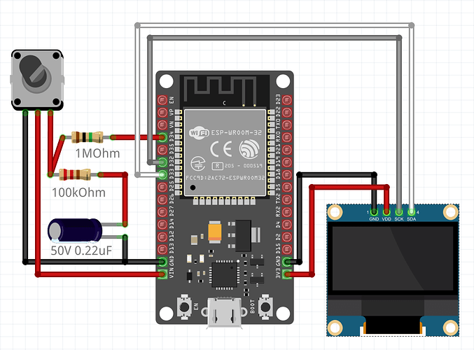
Since the ADC (and any other pin) is only rated for 3.3 volt then 146% seems reasonable if you give it 5 volt.
Which you shouldn’t.

My advice is to remove the 5 volt input to the ESP and just be happy it didn’t give you “no pope has been selected” smoke yet.

2 Likes

I hardly understand your description.
Try with this:

sensor:
  - platform: adc
    pin: 34
    name: "pot_position"
    id: pot_position
    accuracy_decimals: 0
    update_interval: 200ms
    raw: false
    device_class: voltage
    attenuation: 12dB
    samples: 5
    unit_of_measurement: “%”
    filters:
      - calibrate_linear:
          - 0.1 -> 0.00
          - 2.5 -> 100.00

the pin wich is used for display voltage is connected with resistor (1mohm) so it recieves only 2.5V or less (depend on pot position). thanks for advice, it already secured.

please post a scheme of that circuit.

this is more or less what I got there, other thing I have just tried is this:

sensor:
  - platform: adc
    pin: 34
    name: "pot_position"
    id: pot_position
    accuracy_decimals: 0
    update_interval: 200ms
    raw: True
    device_class: voltage
    attenuation: 12dB
    samples: 99
    unit_of_measurement: “%”
    filters:
      - multiply: 0.00095238
      - calibrate_linear:
         method: least_squares
         datapoints:
          - 0.001 -> 0
          - 2.499 -> 100
  - platform: template
    id: pot_raw
    name: "pot_raw"
    lambda: return id(pot_position).state;

it works better, but the other thing is not good: last 15º of pot range gives to me the same value on screen (the actual voltage on pin is changing, but the percentage is not).

I’ve skipped relay module and potentiometer’s motor, because the work just fine and they are not connected to any contacts of pot’s circuit.

What’s the point of that circuit?

Just use plain voltage divider.


Use any resistor values you have on hands between 1k and 20k as long as the R2 is 2x R1.
5V is the output voltage you want to measure and 3.3V is your analog pin.

With this updated circuit use:

filters:
      - calibrate_linear:
          - 0.0 -> 0.00
          - 3.3 -> 100.00

Ps. I don’t know your potentiometer, but the wiring looks quite weird.
Common pot has completely different wiring, output in the middle.

I need the potentiometer connected to 5V because of manipulated device (ventilation controller - is not in the scheme) this device is setting freequency depend on voltage 0 to 5V, this why the potentiometer is connected to 5V

My question was about the 1M/100k/capacitor circuit.

my mistake, you right, the output is in the middle

1M/100k/capacitor circuit is done by one manual from the web, the guy told that it is important for connect potentiometer that way because of stability and security of esp32

May I suggest to disconnect everything before you fry your pot and Esp.
If you have some documentation about the digipot pinout, feel free to post it here.
Conventional pot has pinout like this:

And your resistor-capacitor circuit is absolute no-sense to me.

1 Like

this is correct scheme:

To my opinion, you have 5V ang GND swapped.

this is not digipot, this is motorized potentiometer, here is datasheet:

https://www.mouser.es/datasheet/2/15/RMP_RK16-1370992.pdf

however, it work (I left it like 12 hours operating), only thing I don’t like is calibration of the sensor, and it’s communication with potentiometer, as I said I can not adjust calibration properly, from 0 to 100, and also it looks like potentiometer have a non-visualized range (about 15º at the end) but the voltage is changing at this range (measured by external voltimeter) and at the maximum point it is ~2,5V (thanks to 1MOhm resistor). I thinked it is sript issue…

The pot part is just regular pot.
So use conventional wiring scheme. Remove your resistor-cap circuit and insert the voltage divider I posted earlier and post updated scheme.

1 Like