Hi all,
I’m building a tv cabinet that will raise and lower the tv using a linear actuator.
I want to be able to control this via HA frontend and also using Alexa.
I’m very grateful for the help @ssieb has provided over on Discord. We’ve got the code to validate in ESPHome. However nothing actually happens when pushing the button on HA Frontend.
To give as much detail as possible, here are the specific parts I’m using.
I would say if you have a ESP32 you will need 2 relays. One for open and one for close
You will then need to switch the relays via your esp32 - search YouTube for this
through the relays you will need your power supply of 12V to run to your actuator. One relay wired to open wire and one relay to close wire. Both wired to the NO (normally open) contact of the relay.
update your code
Q: Can you adjust the limit switch on the actuator? if you can then it will stop where you set it and time is not required only for the relay to stay on for a given time just longer than it takes for the TV to go up and down… or you have to make the cabinet suit the actuator as I see yours has a limit switch but not sure if it is adjustable.
you could wait for this one… is not out yet but I think it would work with your 12VDC actuator and power supply Shelly Pro 2PM. Looks like it will also need update firmware for roller shutter that is coming.
get a actuator (with a adjustable limit switch unless you an make the cabinet perfectly to suit the stroke of the actuator) & power supply that is 24V DC
Wire as per Shelly instructions.
Connect Shelly to your network.
HA will see it and automaticity ask you to configure it.
Thanks @Blacky. I was wanting to utilise H-Bridge but will look into going the relay route.
If possible I’d prefer to keep it all ‘in-house’ rather than using yet another app. It gets too hard to manage when there’s numerous apps involved.
No the limit switch is not adjustable on this particular actuator.
I don’t like using the app and I don’t like cloud base things this is why I chosen Shelly. You don’t have to use the app you can use your browser and the ip address and never download the app or connect to a cloud. The new “Device Link” in HA makes it even easer to go directly to the browser of your devices so it really easy to manage in one place.
The shelly will have all your setting you will need and more out of the box.
How are you powering the esp32? What you linked has an input voltage: 3.3V~5.5V. 12v is over spec. What you can try is using the pwm fan component. You’ll be able to turn on the relay and have a slider for the pwm output. Just to test if you can get it to move.
This sounds like what ESPhome calls an ‘endstop cover’ which is something like a windowshade (or even a garage door) that is normally found ‘open’, ‘closed’, or in transit. Some covers stop in-between, but you probably want only the fully ‘open’ and fully ‘closed’ states.
Usually, those endpoints are detected by limit switches, not by runtime of the motor (e.g. what if the motor runs slower when lifting than it does when lowering the load?).
Consider using an adaptation of that existing component, and limit switches to tell it when it has reached one end or the other. (add a timeout to turn the motor off if it ever runs far longer than it should take to reach either end, such as if there’s a jam-up that stops motion)
Fewer gears will be stripped and fewer motors burnt out.
Yes. Really? Excuse my ignorance but can I ask why?
I’m using an ESP32 to operate a garage door and have it powered the same way without any problems thus far…
Yes I do only want fully open or closed.
It sounds like the endstop would only be reached if it can fully extend. I’m not certain that this will be the case which was why I was wanting to rely on runtime. However you bring a very good point that raising would likely take more time than lowering.
When you suggest using limit switches are you referring to adding some sort of a switch / magnetic reed sensor?
Not being familiar with the device you’re planning to control, I’m just describing principles, mostly.
Yes, I would want there to be some kind of sensor (e.g. limit switch, IR beam, etc) to tell the control system when the extent of travel had been reached. i.e. close the loop: When the controller runs the motor to extend, it has something tangible to tell it if/when that goal has been reached of if something failed.
Open-loop systems (that cause actions without getting success/fail signals back) can be more prone to fail or undesired results.
If limit switches aren’t feasible, you may want to consider this as an alternative:
As this is usb C rather than micro b, usb c cables are a little better. Patch cables though, can get away with supplying as little 100/150ma. It’s hard to tell what your getting in terms of wire quality.
When troubleshooting it’s best to eliminate that factor. Your mm readings look low, I’d expect over 2.6v. That’s about 75% of an esp’s pwm output.
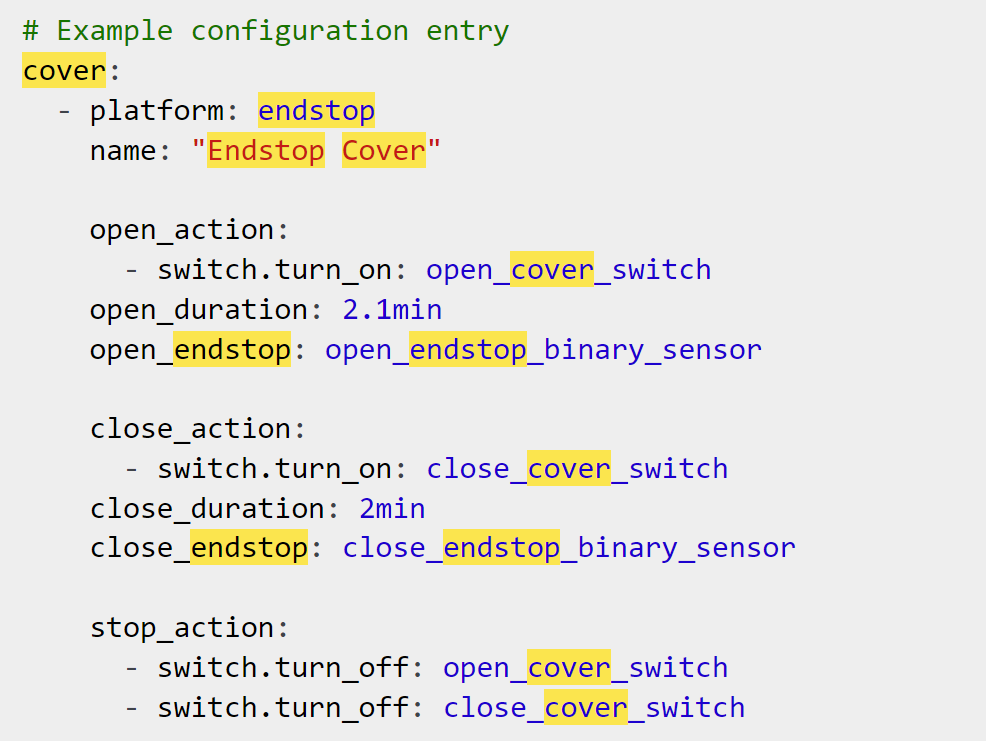
I’ve taken this from Endstop Cover — ESPHome
Without specifying any pins, how can this endstop cover work?
Am I missing something here? Is there other sections of code required to work in conjunction with this endstop cover?
Thanks and apologies if this is a stupid question.
Additionally you will have to define the following:
open_cover_switch (IN1 on your H-Bridge)
open_endstop_binary_sensor (a reedswitch or endstopswitch in the open position)
close_cover_switch (IN2 on your H-Bridge)
close_endstop_binary_sensor (a reedswitch or endstopswitch in the closed position)
You will also have to turn on the enable pin on your H-Bridge. This doesn’t have to be a PWM signal, if your planning on running the actuator always on the same speed.
Are you planning to use the entire stroke of your actuator? If so, the cover platform endstop is probably not the best cover platform to use, as the build in endstops in the actuator are usually not accessable. A timed cover would in this case definitely be easier to install.
Would you mind explaining how to turn on the enable pin on the H-Bridge?
I’m wondering if this is why I’m not getting the expected outcome with my original post?
I’d love to understand why it didn’t work rather than simply abandoning it and going a completely different route.
Good to know I don’t need to worry about using a PWM signal as speed will not vary.
I had built the cabinet on the basis that I would be using the entire stroke however I’m not absolutely certain that my plans have translated to reality.
yes. I haven’t used the “interlocks” before so i’m not sure about them. Doesn’t mean it’s wrong i’m just not familiar with them
On your h-bridge module the enable pin is labeled as “pwm”. You can supply a PWM signal, or you can just turn it on entirely (which would basicly be the same as a 100% PWM signal, aka full speed). For testing purposes i would just keep it simple and just turn it on and off. You can always add a PWM signal later on if you want to decrease the speed. Just look at the table you posted in your first post. “IN1”, “IN2” and “PWM” defined as switches give you full manuall control over your actuator. The cover element (easier automations) can be added later on when everything is working properly.
that’s good. Because if you use the entire stroke, you can just use the endstops in the actuator; no need to add additional ones. Since the build in endstops probably aren’t accessable to attach to gpio’s, the only downside to this is that there is no feedback whether the actuator actually reached its end position.
However, this is all just the software side of things. Have you tried moving the actuator by just connecting it directly to the power supply? Were you able to move the motor, aka, was the power supply up to the task?
Thanks for taking the time to answer my questions.
With regard to your comments on the h-bridge, what do I need to change in my code?
Am I simply removing this line: frequency: “50Hz” so that 100% PWM signal is being used and also removing the cover: component entirely?
Yes the actuator works perfectly when powered directly.
Enable: has to be on for the motor to move. If its off, the motor will be idle regardless of the states of the other two switches. Motor forward: if on, the motor moves in direction 1, untill it reaches its endstroke (or is manually deactivated) Motor reverse: if on, the motor moves in direction 2, untill it reaches its endstroke (or is manually deactivated)
I would avoid activating motor forward and motor reverse at the same time for now. Theoretically this should brake the motor, but i’m not sure what your actuator/motor-controller do in this case. Later on the cover: component will make sure this doesn’t happen.
You still have your GPIO3 declared as PWM (ledc). Just take that out for now. You only need the three switches (and offcourse your wifi credentials). Basicly a fresh new esphome node, and only add the three switches to it.
Perhaps you could also post a picture of your wiring?
Have you allready tried powering the esp32 directly from the “5VO” pin of your motor controller? That should work and is actually quite a neat solution for your setup. In that case you don’t need the 5V USB charger anymore and you automaticly ensure the common ground between motor controller and esp.