This is a project still in progress. I wanted to post to get feedback and help (which I’m sure I’ll need at some point).
I just installed a Quietcool ES-6000 whole house fan. I have the bluetooth controller, but I’m not seeing a good way to integrate with HomeAssistant. Since I finally got my wife hooked to this control system (WAF = 100%), she asked, “is this going to be on the control panel?”
After reviewing a few projects/howtos on this site and on reddit, I decided to go in another direction. The ones I see have a few limitations:
- one is based on Zwave and I’ve done my best to remove all Zwave in favor of wifi and leave my Zwave network dedicated to my deadbolt locks (got burned by a chatty node in my vacation rental home that had me sending out the maintenance guy twice a week to change the batteries!!)
- one is based on shelly 2.5. good solution, but i wanted to be able to control on/off and speed (2 speeds on my ES-6000) AND to be able to control with a physical switch as well.
- one is based on a shelly 1pm AND a shelly 2p – not for me
- a few are based on the Quietcool wifi controller that is now discontinued
If I were willing to switch to 100% wifi controlled, this would be easier, but having the ability to switch manually is a requirement. But, I can’t just have a mechanical switch parallel to the wifi switch because if you supply power to both the high and low lines simultaneously, your fan stops working permanently.
So, my plan is to leave the QC controller in the box (maybe I’ll sell it on ebay) and make my own controller. The fundamental wiring scheme is:
Fan requires a 120vac power on the black/white lines - AND - fan requires 120vac on EITHER the yellow (high) or the red (low) speed line.
Here is a quick truth table:
| Power | High | Low | Result |
|---|---|---|---|
| Off | Off | Off | Off |
| On | Off | Off | Off |
| Off | On | Off | Off |
| On | On | Off | Fan runs at High |
| Off | Off | On | Off |
| On | Off | On | Fan runs at Low |
| Off | On | On | ?? |
| On | On | On | PERMANENT Off |
Now, some solutions trust that a couple of single pole relays will handle this – I’m not so trusting (see above for why ![]() ). I want DT relays for the speed so that only one state is physically possible.
). I want DT relays for the speed so that only one state is physically possible.
So, here is my plan:
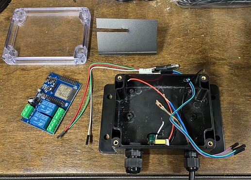
one of these (2ch relay with ESPHome/ESP32)

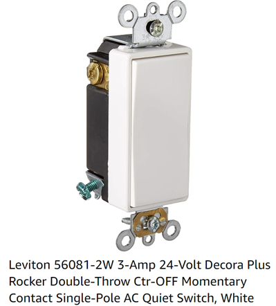
one of these (SPDT decora momentary rocker switch)

The fan power will be connected to relay channel 1 / NO. The fan speed high (yellow) will be connected to relay channel 2 / NC and fan speed low (red) will be connected to relay channel 2 / NO. This means the fan will default to high unless the relay is energized in which case it will run on low – and there is no chance for both high and low to be powered simultaneously (see above for why ![]() )
)
The decora switch will be connected to GND on the common side and each pole will be connected to a GPIO on the ESP32. With this setup, I can use the physical switch to control the “controller” – push up and the on/off status changes, push down and the speed changes.
With this setup, I can control everything from HA but also from the switch without having to worry about accidentally powering both high and low simultaneously (see above for why ![]() ) and I don’t have to worry about someone turning it on with the switch then I can’t turn it off with ESPHome. The controller will be in the attic near the fan and a low voltage, three conductor wire will be run inside the wall to the momentary DT rocker. I don’t know how reliable these modules are in terms of needed to be rebooted, but I can also run another conductor so I can reset it without having to go into the attic (maybe I’ll put it on a wall in the closet under all this stuff?)
) and I don’t have to worry about someone turning it on with the switch then I can’t turn it off with ESPHome. The controller will be in the attic near the fan and a low voltage, three conductor wire will be run inside the wall to the momentary DT rocker. I don’t know how reliable these modules are in terms of needed to be rebooted, but I can also run another conductor so I can reset it without having to go into the attic (maybe I’ll put it on a wall in the closet under all this stuff?)
Additionally, I would like to add some status LEDs to the ESP32 and configure them to reflect fan on/off and high or low speed. I think I can do this from ESPHome without having to write an automation (but I’m open to being corrected if someone knows otherwise).
Thoughts? I just started ordering stuff, so feel free to pokes holes in my plan. These fans are expensive so I don’t want to do anything stupid. I’ll keep this thread updated with progress and I expect I’ll need some help with the ESPHome configuration (mainly to integrate the physical switch and the lights) – I’m hoping I can count on this community!!


