RainBird ESP-RZX with Tasmota piggyback

Hello,
I tried and succeeded to a certain point to use an old irrigation controller RainBird ESP-RZX (6 valves) together with ESP32 running Tasmota. For the moment, I can control the triacs through HA, have set timers and rules, but I also can use the controller the original way.
I identified the gates for triacs, measured voltages and connected the gates with ESP32 GPIO pins through 200ohm resistors. This way we can trigger by ESP command or by original command.
Next step is to analyze the voltages, lower the resistors values and trigger the gates only if we want to, even there’s command from original controller.


Purple wire is connected to GND - TP8;
Grey wire is connected to MV (TP42) = main valve, can be used as a 7th valve but be aware that the controller triggers this one together with any of the others;
The remaining 6 wires are connected to V1-V6 gates, TP45, TP48, TP51, TP54, TP57 and TP60


Used some leds for testing. Also used a 10ohm resistor to connect GND, not really necessary;


There is a lot more to improve, if someone is interested in this project I will gladly add info and also will be happy to learn from others.

1 Like

Hi maiandrei,

Let me share that this project was one “in my the drawer”.

Some time ago I tried to use the accessory port in order to connect and “reverse engineer” the signals with a serial sniffer, but I could not get anywhere, without clues.

I see you got another nice idea directly connecting to the triacs.
Some questions, since I will probably “adopt” your idea :blush:.

  1. Is the Rainbird controller connected to the main power?
  2. Can you use the controller independent from the ESP32?
    a. There is no integration, for example, between the configured schedules over them, correct?
    b. They are two independent systems?
  3. I think the controller board runs on 24VAC, and also the triacs, how did you power on them?
  4. Are you powering the ESP32 from 24**VAC** with a stepper down 24VAC=>5VDC?
    

Very curious and thank you in advance!

PS: On another hand we could go with simple trigger the Arduino to the switch buttons and create a kind of “macros” to interact and program the interface :slight_smile:
There are 10 buttons and the reset, so need 11 pins. Fine with a ESP12E or ESP32

NV

Hi NV,

Glad I can help. Straight to your questions:

  1. Rainbird board is powered by its original 24Vac transformer.

  2. Yes. If ESP32 is unusable by any reason, you can use Rainbird controller the old way. For example, I hit the Reset button in Tasmota and got ESP32 disconnected from WiFi while in holiday. Just had to call mother-in-law and tell her to press the green button on RainBird Controller.
    a. Correct.
    b. Yes, any of them can trigger the triacs.

  3. RainBird board uses the 24Vac only for valves. It has a 3V regulator for its controller, but I didn’t want to use that because it gets hot already. I only connected ESP32 GND to controller’s GND, and ESP32’s IOs to triacs’ gates, the same way the original controller does - through resistors. The valves are connected to 24Vac directly on one line and, by the triacs, to the other line.

  4. I used a good old USB 5V phone charger.

I had only one night to get this done before vacation, and since then I didn’t modify anything because it’s working like a charm (read I’m a lazy person). Scheduled the valves in Tasmota to run at sunrise and I also can toggle in HA.

PS. Controlling the switches could be a great idea if we could get the output too (kinda what’s displayed). Otherwise I don’t want to think what happens when a bit in the sequence gets lost (eg short blackout or brownout)

Hi maiandrei,

Thank you for your feedback. and these details. I think I will go for your idea!

ahah :slight_smile: Mother-in-law backup is also nice :)!

Bonjour Ă  tous,

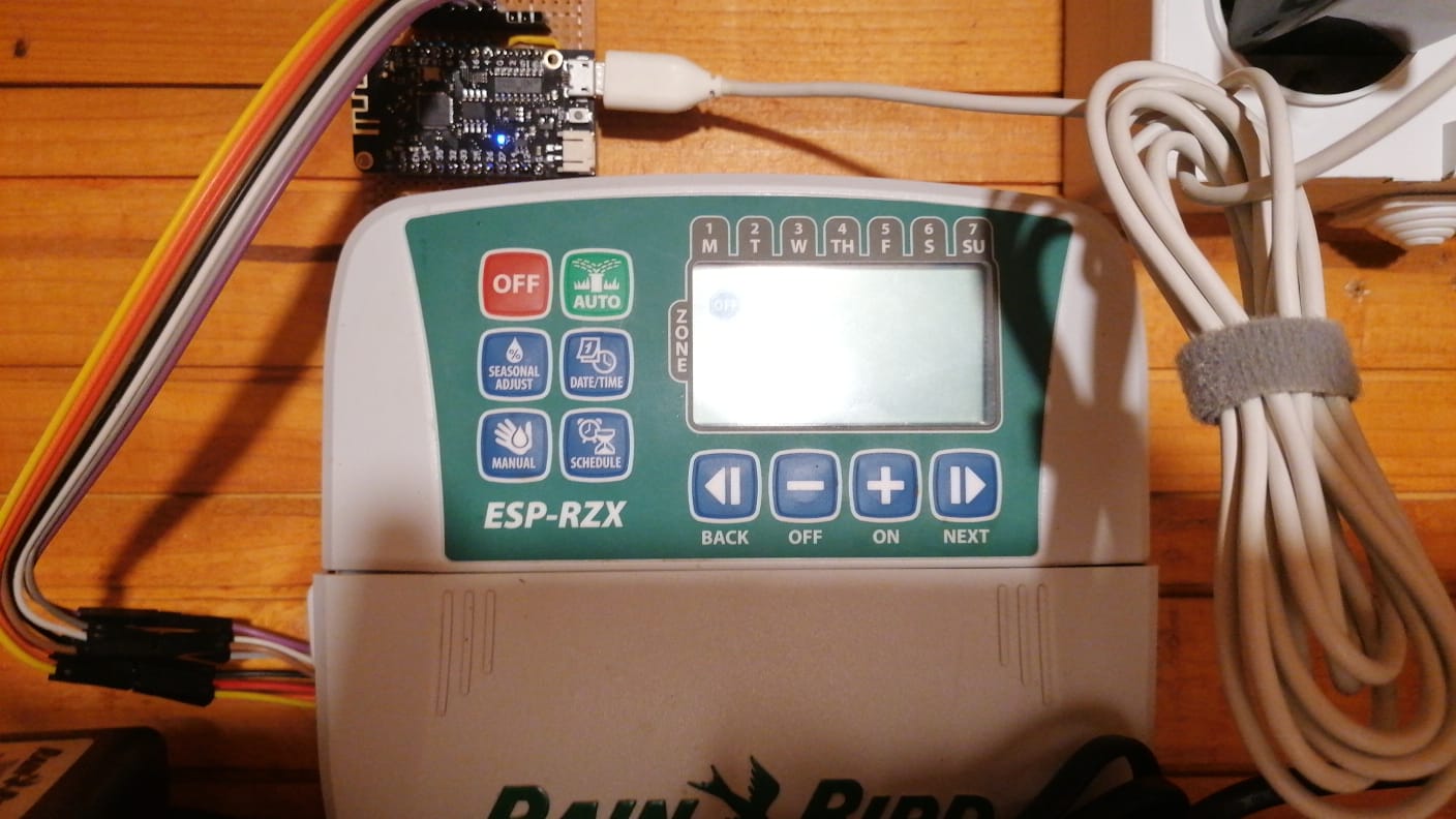
Je partage ici l’avancement de mes investigations sur le port ACCESSORY (5 broches) du programmateur Rain Bird ESP-RZX, utilisĂ© notamment par le module WiFi LNK.


:electric_plug: Pinout mesuré (de la gauche vers la droite)

Pin Fonction Tension mesurée
1 +12V OK
2 GND OK
3 +5V OK
4 Signal logique ~3.3V
5 Signal logique ~3.3V

:zap: Mesures électriques

  • Pin 4 → GND : 180 kΩ
  • Pin 5 → GND : 100 kΩ
  • Pin 4 → +5V : ∞ (aucune continuitĂ©)
  • Pin 5 → +5V : ∞
  • Pin 4 ↔ Pin 5 : 4.3 kΩ

:point_right: Les deux lignes logiques (pins 4 et 5) sont donc faiblement tirĂ©es Ă  la masse et couplĂ©es entre elles via une rĂ©sistance interne d’environ 4.7 kΩ.


:zzz: Comportement sans module connecté

  • Les pins 4 et 5 sont synchrones
  • Signal carrĂ© d’environ 50 Hz
  • Aucune trame de communication observable

:zap: Détection de présence du module

En injectant un signal sur la pin 5 synchronisé, mais opposé, avec la pin 4 (via un ESP32), le contrÎleur :

  • quitte le mode idle
  • semble Ă©mettre des trames numĂ©riques

:point_right: La prĂ©sence du module semble ĂȘtre dĂ©tectĂ©e par une activitĂ© sur la ligne DATA (pin 5).


:satellite: Communication observée

Une fois activé :

  • Pin 4 : signal rĂ©gulier (horloge)
  • Pin 5 : signal synchronisĂ© avec contenu variable

:point_right: La communication semble ĂȘtre du type synchrone.


:x: Tests de protocole

  • DĂ©codage UART : invalide
  • Signal incompatible avec UART

:white_check_mark: 
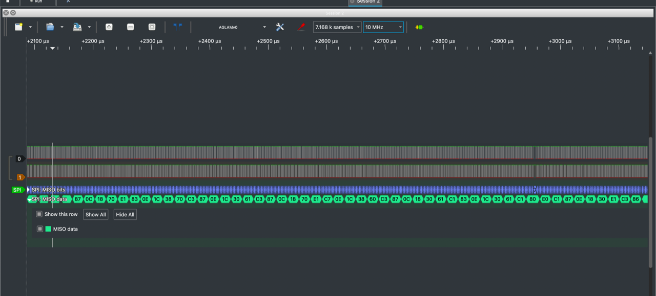
Trames capturées en mode SPI

Exemples de données obtenues :

20 43 80 04 08 10 A1 00 02 02 


ou

02 07 16 80 02 00 43 80 04 


:point_right: Les données sont structurées et répétitives, ce qui confirme une communication numérique protocolaire.


:warning: Comportement important

  • Si l’activitĂ© sur la pin 5 s’arrĂȘte :
    → retour immĂ©diat au signal 50 Hz

:point_right: Le contrÎleur nécessite une activité continue pour maintenir la communication active.


:wrench: Tests réalisés

Injection active (ESP32)

Code utilisé :

int inPin = 22; //pin 4
int outPin = 23; //pin 5

void setup() {
pinMode(inPin, INPUT_PULLUP);
pinMode(outPin, OUTPUT);
}

void loop() {
int state = digitalRead(inPin);
digitalWrite(outPin, !state);
}

Résultat :

  • activation du bus
  • apparition de trames
  • mais donnĂ©es perturbĂ©es

Injection faible (impulsions courtes)

  • impulsions de quelques microsecondes synchronisĂ©es sur l’horloge
  • trames propres observĂ©es
  • mais pas de rĂ©ponse fonctionnelle

:jigsaw: Conclusion (faits établis)

  • Le port ACCESSORY utilise une communication synchrone
  • La pin 4 agit comme horloge
  • La pin 5 transporte les donnĂ©es
  • Les deux lignes sont couplĂ©es via ~4.7 kΩ
  • Le contrĂŽleur reste en mode idle sans activitĂ© sur DATA
  • Une activitĂ© sur la ligne DATA est nĂ©cessaire pour activer la communication
  • La communication s’arrĂȘte immĂ©diatement si cette activitĂ© cesse
  • Le protocole n’est pas de l’UART

:dart: État actuel

  • Activation du bus : :heavy_check_mark:
  • Capture de trames : :heavy_check_mark:
  • ComprĂ©hension partielle du fonctionnement physique : :heavy_check_mark:
  • DĂ©codage complet du protocole : en cours

Si certains ont dĂ©jĂ  travaillĂ© sur ce port ou le module WiFi LNK, je suis preneur d’échanges :+1: