as I noticed that my Pi 4 4Gb became recently very hot, I upgraded my case by two fans. I used this nice guide but dicided to use one to blow cold air in and one to blow the hot air out:
I used GPIO4, one 5v and one GND pin.
Once the circuit was built and wired, I added the fans as a switch in the configuration.yaml:
sensor:
- platform: rpi_gpio
  ports:
    4: Raspberry Pi Luefter
In addition, we need the CPU temp for automation purposes, thus I used the command_line platform to generate a new sensor:
- platform: command_line
  name: CPU Temp
  command: "/bin/cat /sys/class/thermal/thermal_zone0/temp"
  unit_of_measurement: "°C"
  value_template: '{{ (value | int / 1000) | int }}'
  icon_template: 'mdi:thermometer'
In normal operation of hass.io and with the fans turned on always, I got the temperature down from 65 to 33 °C. In order to reduce noise and unnecessary ventilation, I wrote the following automation which cools the pi down quickly and then turns off until the next cooling cycle:
Now the fans run for about 2-3 minutes and cool the pi down from > 55 to 35 degrees. In a room temperature environment, it takes about 13 minutes until the fans kick in again.
Finally, some pictures (of course I isolated the wires in between the pictures)
You are aware that these are wired in parallel and that they work together ?
For a motor to act as a generator (unless you have some fancy DC motors with variable field coils) The spindle has to turn faster than the present voltage would run it. Theses are fans, they are in air so their will be constant drag. You imply a suspension of entropy and that soon we shall be able to generate power for a whole city from a single AAA battery.
Where did you learn electrical engineering ?
I just take a look @ the pcture in fullsize.
everything is ok.
btw: yapp i can power a whole city an a single AAA batterie.just ask how big the city is (made out of lego and how long)
@Codec303, it’s technically not powered from gpio (though it is on the header) it from the 5v rail.
The gpio output (3.3v) here is used to drive a transistor.
@Coolie1101, use the cpu temperature as a temp input sensor on a generic thermostat (cooling) to switch the gpio pin off and on Edit: nice case ! I’m playing with the new flirc one for the pi 4
I love playing with fans, and one thing that would keep me playing here is the on/off cycling of the fans using the OP method. I would definitely be after pwm control likely with pid. That may be an obscure order for an ha pi, but I do it all the time with arduinos. Maybe a similar solution using pid+pwm can be ported over for pi’s running ha. With pi4’s running so hot, I imagine such a feature would be widely appreciated.
Yeah no free energy, but there will be a collapsing magnetic field at turn off, and that could bring issues if not redirected with a diode. This is entry level ee right? …switching inductive loads and all. So really Jan is not far off base here, and certainly doesn’t deserve the ‘cracker Jack degree’ comment imho.
Do you know what the english translation of his phrase was ?
And how do you think the transistor will react in that circuit ?
Have you worked much with decelerating DC motors, especially in a mechanical load context like this ? (fan drag)
Power a 5v fan (with a volt meter across the 5v leads) then disconnect the power, see what happens. Then rinse and repeat with the transistor.
But then you want to exacerbate the switching situation by moving to PWM, It will work, but it does undermine your argument. There would be no harm in Jan putting a blocking diode in and you putting a reverse diode in (you weren’t arguing the same point) but as an Electrical Engineer I would say that neither would add any benefit and his would just reduce the voltage (that AND PWM would increase iron losses).
You are also ignoring that this is Tobi’s solution and he has obviously not had any issues with it.
Not sure how you’d implement PID on the hardware you mention, probably by ignoring any Integral and Derivative components and just using the Proportional to determine ‘Nudge’ Direction (though that would work, but it’s hardly PID ??? any counter to this I’d be impressed with).
I’ve worked with even some large scale multi-variable control systems that haven’t performed ‘too well’ and later been replaced with ‘nudge and wait’.
THAT is a VERY nice fan.
The only problem I see with it in the pi must run caseless (so it says in the blurb)
But at a max of 52°C with 4 cores at 100% - impressive (though surely that’s dependant upon ambient ?)
You could control this as the OP does
He runs it down really cool so takes 15 mins to switch back on.
Heat dissipation works best with a high differential BUT your processor will last longer the cooler you run it.
It’s personal choice on the set points.
Personally, I’d prefer passive cooling systems, I’ll post a couple of links. The flirc case (the designer tells me) has 3 to 4db ‘better’ wifi signal than a bare pi. I’ve never had problems with it so it at least doesn’t seem to hurt.
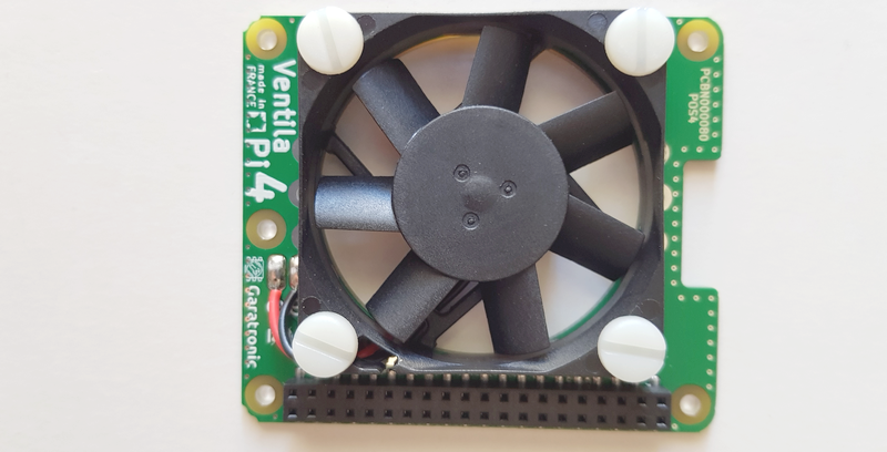
According to the pictures you can easily access the two wires and built the small circuit with one transistor and resistor. The board also offers the option to go without wires and place the components directly on the pcb
This is correct, I found this picture with the fan in the official rpi4 case: there is no way to close it, even if the “hat” seems bigger enough to cover all the upper part of the board
Since I’m looking for a silent solution, I might consider this passive systems as well. I really like the FLIRC case!
I’m afraid the pictures show two different boards, in one version the fan is mounted on a proto board, in the other one the fan is mounted on a more “custom” board (also here)… anyway, I’m sure it is possible to place the small circuit in a nice way also on the second board
Hmmmm !
I feel a compromise comming on.
It’s a shame that when you want a ‘nice bit of kit’ you are either forced to buy into their whole ecosystem or leave it looking like a dogs breakfast.
That’s what I liked about Tobi’s system (it was smooth and neat), the only detractor I saw were the screws in the top, (well you ‘may’ need to replace a fan). I think if I were doing it again (not that I did it in the first place) I’d try hot melt glue and the inside (after cutting the fan holes of course).
But that’s just a nit-picking improvement on a job already well done.
But I also hear you in that the location sometimes demands a quiet solution.
Roger that, the transistor in the OP method would be absorbing the load, which would be fine if it were a typical fet with doide built in. Yeah, the switching would become even more an issue with PWM… I figured PWM would imply using a driver fet at least. I also agree with you that in this case using zero i and d would probably be more than enough to accomplish the desired behavior. How to do it with said hardware IDK… this is why I mentioned possibly porting something over from arduino-land to add a pid feature to the pi (accessible by ha of course).
Being a ‘more hardware than software’ type myself, I’d probably do it by just adding a dedicated circuit and thermistor using parts from my scrap bin, LOL. However I’m sure with all the dev talent roaming around these parts, it may be feasible to do this with just a fet and pi. Of course that would be ideal; and the fet would allow 12V fans so much more to choose from.


 I also agree with you that in this case using zero i and d would probably be more than enough to accomplish the desired behavior. How to do it with said hardware IDK… this is why I mentioned possibly porting something over from arduino-land to add a pid feature to the pi (accessible by ha of course).