Hi @on6ba what type and value were the diodes you used and was it the digital out or analog one?
1N4148, regards.
Yes that would be great. Or PM me.
That doesn’t make any sense on a digital out. All what it will do it decrease the the signal voltage to a level that cannot be reliably recognized by the MCU as a binary high anymore. It will not reduce false triggers, it will simply miss them. It will also miss legitimate triggers.
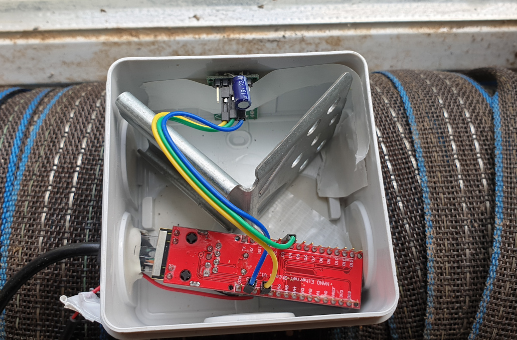
The main problem with the RCWL is it’s extreme sensitivity to wifi. Having a wifi transceiver nearby, such as an ESP, will cause huge problems. And ‘nearby’ can be over a meter away, in more extreme cases. I could bet that nine out of ten cases where people report false trigger problems with this device, it is wifi interference. I have a setup with an RCWL monitoring a walkway outside, and it works flawlessly. It uses wired Ethernet with PoE and an Arduino. There’s also a metal shield just in case.
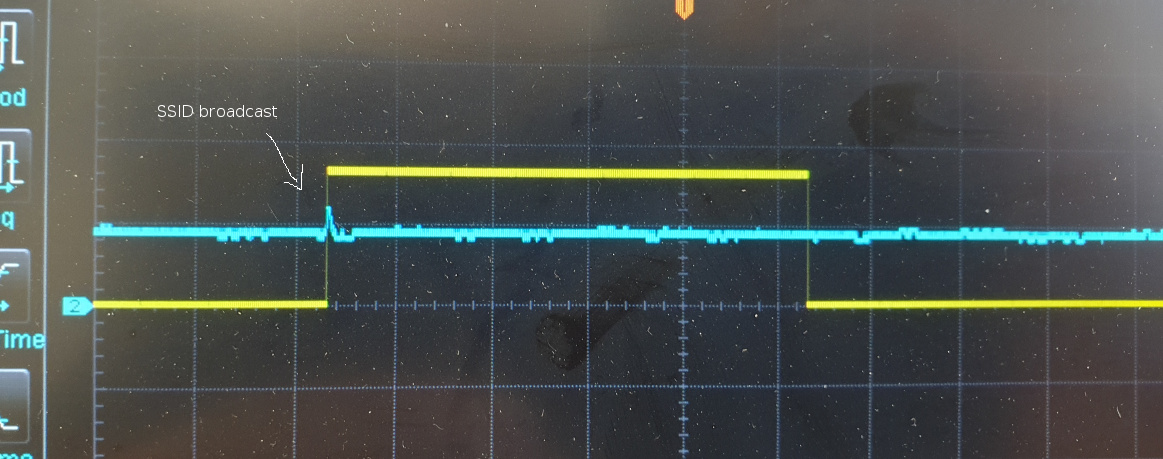
Here are some tests I did with this device in the lab. In addition to the usual connections, I soldered a wire to the chip directly, so to get the analog signal before the comparator and see what goes on in there:

The analog signal level is kept at a constant reference level if there is no movement. When an object approaches the sensor, the voltage will increase. And it will decrease from this reference level when an object moves away from the sensor. As soon as the voltage deviates from the reference bias, a compensation circuit kicks in and forces it back to the reference level. The amount of compensation is proportional to the rise time of the original signal level change. So a fast movement will trigger a fast compensation and vice-versa. The compensation can (and will often) overshoot before it compensates itself. This is why the analog signal fluctuates so much up and down even with linear motion towards the sensor. As soon as the signal deviates too much from the reference level, a comparator will trigger the digital output high. It goes back to low with some delay after the analog signal reached the reference level again.

The yellow channel is the digital out, the blue channel is the analog one from the chip.
A - I start moving towards the sensor. The analog voltage increases, goes over the threshold and the digital output triggers.
B - The compensation kicks in and draws the voltage back to the reference. This process repeats multiple times until I stop moving.
C - I stopped moving and the compensation slowly brings the analog signal back to the reference level.
D - The internal delay was reached without movement and the digital output goes back to low.
Now I created a wifi hotspot on my mobile phone. I put the phone on the desk, 30cm from the RCWL. I asked a colleague to connect to the hotspot with a tablet from an office across the hallway. This is what happened:

You can clearly see the Wifi signal appearing in the analog signal. The first peak was too small to reach the threshold of the comparator, but the second one triggered the digital output. This was with a wifi transmitter (my phone) 30cm away from the sensor.
Now I put the phone 1 meter away from the RCWL. I also disconnected the tablet from its AP and just let the AP idle. It will still advertise its existence every so often. And it will still create false triggers:
The peak in the signal is lower, but the wifi transmitter is now 1 meter away. It’s still enough to trigger the comparator and as such a false trigger.
So as far as I see it, there is no way to use this sensor in combination with any MCU that emits a wifi signal in any reliable way. It might work sometimes. But you can never be sure.
This is my own little quick and dirty test setup with the sensor at home. Works really well, no false triggers in over a week. But as I said, it’s entirely wired and connects to HA over MQTT. It monitors a walkway outside through the window, sensitivity is around 7m.
5 Likes
Wow thanks @HeyImAlex this is very interesting and good researching .
I had one on a ESP8266 and it work fine for about a week and then for some reason false triggers started.
So basically this can’t be used in any house that uses wifi.
Back to PIR then.
You can use it in a wifi environment, but you need to keep it away from wifi transmitters that are too close. A clearance of 1m to 2m should reduce the amount of false positives due to wifi interference significantly. The worst you can do is connect it to an MCU with onboard wifi (like the ESP, Wemos, Sonoff, etc) within the same enclosure.
PIR has other issues, especially outside. A combination of both might be a good approach. Or something completely different, like a ToF sensor.
1 Like
Some updates on my setup, if someone is interested. It worked very well for about 3 weeks. No actual false triggers, except for the random foxes and neighbors cats running around at night 
That is, until yesterday. That is when it started to fire false triggers like crazy, every couple of minutes over many hours. What happened ? Well, it started to rain…
![]()
So that thing is not only over sensitive to Wifi, but also to rain. It kinda makes sense if you think about it, rain is a big aggregated body of moving water after all. But it also makes this sensor totally useless for my use case. Even an inside sensor was triggered due to heavy rain from outside of the window. I will still try to make the module less sensitive by adding a resistor to the R-GN pads. We’ll see how that goes.
I also tried the HFS-DC06. This one was even worse (and more expensive) and pretty much unusable outside.
In the end, this is all cheap Chinese stuff. They’re designed to cost a few cents to manufacture, not to perform well. They are fun, work surprisingly well in a controlled environment. But as soon as you actually start relying on them for some automation, you will run into their failure modes. I started looking around for higher quality alternatives. Bosch is doing some heavy duty outside rated microwave sensors, I’ll look into those. Of course they cost like 50 times more than an RCWL, but reliability has a price I guess
2 Likes
Kinda talking to myself here, but it’s been over a month now that my RCWL based motion sensor is in testing, so I thought I might write down my final observations running the module in an actual every day use scenario. For future reference, maybe someone will find it useful
So I’m very happy with the module after all. After more than a month of testing, I’m now going to start using it in actual live HA automations.
-
Adding a 1MΩ resistor to R-GN has helped tremendously. No more false triggers due to natural elements (stress tested in two storms with very heavy rain), blowing wet leaves or similar. The module is way too sensitive without it, they should have added a small trimpot on those pads by default. Interestingly, adding the resistor will not notably affect the detection range, which stayed at around 6-7m outdoors through a window, but it will affect the threshold for the trigger. So a larger object needs to move for it to trigger, rain and blowing leaves won’t affect it anymore. The neighbor’s cat still does though

-
The module is affected by high temperatures. I originally left the wallbox containing it (see my image above) open for testing purposes. It sits on a window sill inside. The problem was when the sun was shining through the window directly on the module, heating it up. It would not detect anything farther than a few cm anymore. Cooling it down brought it back to normal. Closing to box and adding a larger plastic cover as sun screen above it solved the problem. Professional microwave sensors have an internal temperature correction btw.
-
RF propagation patterns are weird, completely unpredictable and counterintuitive. That module isn’t a ‘real’ radar and does not have any kind of ranging and digital signal postprocessing. It simply mixes the transmitted and reflected signals and triggers when the phase shift variance over time goes above a threshold. The more reflected signals you have (multi path propagation usually due to metal objects around the sensor), the more likely it is that moving bodies will induce a high phase variance. Moving or turning the sensor a little, only a few cm sometimes, will completely change the detection pattern. Metal objects around the sensor will reflect the signal and create new paths, which will increase sensitivity (sometimes too much).
-
Shielding the sensor works really well. Originally I put in a small metal angle to shield the sensor from possible interference from the Arduino (see pic above). This had an interesting side effect of shielding the sensor from basically anything behind it. The sensor box is in a stable building and the horses had a tendency to trigger it from time to time when moving around. That little metal piece solved that problem entirely. Note that the shield is not grounded. Grounding it would make it not work anymore
 When not grounded it probably acts as a mirror for the transmitted signal.
 -
These boards were produced using the cheapest process available. There’s a lot of variance between individual boards, not one board behaves like another, the manufacturing tolerances are huge. If you adjusted your detector to work well in a certain location, don’t replace the sensor board or you will have to start all over. Some RCWL boards simply don’t work at all. Two out of the five I had are just unusable. They kinda work in the lab, but they’re totally unreliable in a real world situation.
-
There’s a lot of strange information about this device online. Just to clarify a few of the misconceptions floating around on various forums. You don’t need some over the top decoupling with ridiculously large caps, pi filters and whatnot. The board itself already has plenty of small decoupling caps soldered onto it. A single 22µF cap over Vcc is enough. Some people suggest the modules works better when powered with 12v or more rather than 5v. That’s nonsense. The board has a 3.3v voltage regulator onboard which powers the entirely internal circuitry including the RF part.
So yeah, great little sensor. Keep it away from wifi and bring a little time tweaking it (position, shielding, R-GN) and it ends up working surprisingly well.
End of report haha 
14 Likes
I just want to say thanks for posting all this info on this sensor and for your update report! I have a couple of these coming in the mail (hopefully) soon. All this information you’ve posted will be incredibly helpful as I work on getting these set up and testing for my use!
Happy to know it helped someone ! Let me know if you run into issues.
Since I wrote my posts above I deployed a few more of these modules, both inside and outside. Depending on the location they can be a little difficult to adjust, but they all ended up working really well. Some of them are wireless. I ended up using HC-12 transceiver modules to connect them remotely to an MQTT gateway, which will in turn connect them to HA. Since the HC-12 operates in the 433MHz band, there are no interference effects with the RCWL. It also has a much better range than Wifi and uses way less power.
1 Like
To continue the tradition of me talking to myself here, there are some more observations I would like to share on these sensors. I’ve been deploying the RCWL on a pretty large scale now, together with other motion sensor types, in my completely overengineered perimeter motion detection thingy. I live on a pretty large farm, so there’s plenty of space and areas to play around with totally useless absolutely vital intrusion detection technology ! While most of this is from experience in outdoor scenarios and within pretty open barn-style buildings, a lot of this is also valid for indoor use of the sensors.
So what I found out:
-
Some online resources claim (I’ve seen this on at least two yt videos) that if you have multiple RCWLs close by, they do not interfere with each other. That is absolutely untrue. In fact, they massively interfere with each other. This is especially noticeable if each covers its own distinct detection area, but slightly overlap at some point. In practice, this is a very common scenario as you would want some overlap between sensors to avoid blind spots. What happens is that when someone is moving within the RF field of one sensor, it slightly changes its resonance frequency and trips. This change of frequency will affect other RCWL modules in proximity, changing their resonant frequency in turn (and possibly tripping them in the process). This can lead to a cascade effect if you have multiple modules around. Due to manufacturing tolerances, some modules will be more affected by this than others.
Avoiding this is difficult. I played around with sensitivity (resistor on R-GN, see above) and shielding, but the results were unreliable. The only really reliable way is to keep some distance between modules. Or having some RF absorbing structure between them, like a thick wall. -
The above interference issue leads to blind spots. From my experience, a good way to manage this is to alternate between PIRs and RCWLs, having their respective detection fields overlap. If you keep this overlap large, then you will get the added benefit of redundant detection. Depending on how you manage the logic here, you can either use it to increase sensitivity (motion = RCWL tripped OR pir tripped) or make it more robust to decrease false alarms (motion = RCWL tripped AND pir tripped).
-
The detection field of the RCWL is not spherical, but rather in the shape of two elongated lobes perpendicularly aligned to the modules’ antenna (basically to the PCB). You can use that to your advantage by turning the module in a way to orient the lobes towards the area you need the best detection at. Turning the module (even by small amounts) typically has a much larger effect on sensitivity than moving it around.
-
Careful if you mount the module on a wall just under the gutters (which is a nice hidden spot). If you have metal / aluminum gutters, there will be all kinds of weird RF reflections going on. Try to avoid building corners if the gutter outlet / downspout is nearby. Unfortunately this is usually a really good spot to cover a large area. Prefer using a PIR in these cases.
-
Speaking of PIRs. Don’t use these crap AM312 or HC-SR501 that you can find all over the place. They’re just bad. The best PIRs in terms of reliability, false alarm immunity and size I found are the Panasonic PaPIRs. See specs here. While slightly more expensive than the usual China crap, these are industrial type sensors and play in a totally different league than the cheapo ones. They’re easy to add to an ESP, Arduino or Raspberry setup too. They work great in combination with the RCWL module.
-
RCWLs and wifi don’t go along too well if they’re nearby. But sometimes you just need to have them communicate wireless. The HC-12 modules I mentioned above are working great for that. They also have up to 20dBm tx power at 433MHz, which is huge and allows for very long range communication (but may be borderline illegal depending on your local laws, the transmit power is configurable though). They also use very little power in standby, so battery powered sensors are possible. From my experience, there are no interference problems with the RCWL, even if both are within the same enclosure.
So my next projects are some more field testing with 24GHz radar modules like the CDM324 and possibly with Lidar too. I was planning to sprinkle Velodyne VLP16 modules all around the property, but then I noticed that they would be slightly above my budget  So back to cheap Radar modules I guess.
11 Likes
Thank you for your insightful analysis.
A work-around occurs to me: instead of wifi for wireless operation, I am considering ESPnow. The duration of an ESPnow transmission is far shorter than that of standard wifi handshaking.
It should be possible to have wifi disabled, then enable it, ESPnow transmit, and disabled again before the triggering event has even completed, in 10s of mS instead of seconds. The enabling process is also fast (I believe.)
Thus, although the transmission is still a wifi 2.4GHz signal, and will still interfere with the radar, by the time you are transmitting you have already received the triggering event, and ‘false positive’ isn’t possible.
I am still some way from trying this.
Using ESP Now for data transmission would most likely work a lot better than Wifi. As you correctly stated, the transmission retriggering the radar is not a problem as long as this happens only after a legitimate trigger and that you take precautions to not end up in a false retrigger loop (by ignoring the RCWL state during and shortly after a transmission).
There’s one more caveat with ESPs. From the limited experience I have with them on a batch of cheap-as-dirty Ebay sourced clones (I prefer to use other MCUs myself), I noticed that they have a tendency to introduce significant amounts of noise onto the supply lines. Not only their own 3v3 line, but also on the pre-regulator Vin feed. It looks like something (clock oscillator, some RF amplifier stage, whatever) backscatters a lot of RF noise into it. This can also mess with the radar module if you power it over the same supply, leading to things like constant triggers. A small LC lowpass mounted close to the ESP would probably help with that. Not sure if higher quality ESP modules also exhibit the issue or if it’s only with the cheap clones.
Let us know how it turns out !
3 Likes
Thanks for your posts - especially as they drew from your experiences.
After some frustrating tests with an ESP8266 in the same enclosure as the RCWL, I too came to the conclusion that WiFi was the origin of false positives. Currently, I am using LoRA 915MHz as the transceiver which is separated from the RCWL device by ~2m of cable. Thanks for the heads-up on the possible influence of rain.
In passing you did mention what I think is a key feature that should be exploited more: sensor redundancy - ie requiring multiple (perhaps different?) sensors to confirm a trigger. Finally, I did think about playing with the raw analog output - perhaps with some statistical analysis of the pulse waveform - rather than just relying on the conditioned digital output.
Sensor redundancy and sensor fusion are becoming really fundamental concepts in these kind of setups. I agree that they aren’t really exploited enough (if at all) in typical home or small business setups, and they’re rarely seen in DIY. High end commercial solutions use them a lot though.
The great thing about combining a network of multiple and diverse sensors is that they can complete each others information. If done right, this results in reduced noise (much less false alarms) and much higher robustness and selectivity. It really helps in keeping situational awareness even if some sensors are down or temporarily unreliable. The others will compensate for it. Damn, that sounded like a marketing pitch 
At the end of the day, no sensor is perfectly reliable. Each sensor type will have its own failure modes and environmental situations where it will perform subpar. PIRs don’t like hot sunny days. Radars don’t like rain. Both don’t like passing flock of birds or the neighbor cat checking out his territory every night. VMD can have issues with shadows at night under IR. Lidar doesn’t like fog. But all together will be able to give you a very accurate picture of the situation.
Here’s a simple but interesting example. The following three sensors have overlapping detection areas and they’re in a difficult spot. There’s lot of trees around and it seems that bird nesting season is starting early this year. So I get a lot of false alarms on each sensor individually. But if I use them together, things look much better !
The first sensor is an RCWL. The second is a PIR right next to it. The third is another PIR on the other side of the area, a very problematic spot. Despite all the false alarms due to wildlife, every time an actual human walks by, all three will trigger:

I’ve added six new single point LIDARs to my current setup. They will be used to create virtual fences at the major ingress and egress points of the property. While they are just line crossing detectors, they can differentiate between small animals and large ones, like humans (which the RCWLs can’t). So I expect them to add valuable information to the system.
My girlfriend thinks I’m crazy 
2 Likes
So another status report on the RCWL 0516 radar modules I deployed.
The verdict after roughly 9 months of operation now is not very good. A lot of the modules have failed since. As mentioned earlier, these modules use traces on the PCB as capacitors and inductances in a free running (non phase locked) RF oscillator. So even small changes in the shape or dielectric constant of the PCB will affect the functioning of the circuit. These PCBs are produced using the cheapest process available and environmental effects, moisture, solvent evaporation and other chemical changes in the PCB made their frequency shift over time, out of the operational range.
Most of my outdoor sensors failed within the last 2-3 months. The ones placed indoors are less affected, but I also started to notice anomalies lately. I initially tried to replace the failed outdoor ones with other RCWLs I had in my spare part bin. But since not two of them are exactly the same due to manufacturing tolerances, the new ones would often not work when placed at the location of the old ones. So for every replacement sensor I had to fiddle around with different sized resistors on the R-GN pads, placement and orientation, just to make them work again. It takes a lot of time as nothing is repeatable. It’s not a simple one to one swap.
Another annoying property of these modules is their dependence on metal for RF reflections. If you don’t have enough metal within their detection radius, they won’t work as the RF isn’t reflected back towards the module. Earlier this year, two sensors suddenly stopped detecting people. Just like that, out of the blue. And both simultaneously. After much trial and error the culprit turned out to be our tractor we use for making hay bales. It was standing in a small hangar over the winter without moving. And it involuntarily provided the metal these detectors needed to create their RF fields. We hadn’t moved it since I installed them end of last year. When I parked it again at the exact same spot it used to be, the sensors started to work normally again. This extreme dependence on a highly static environment is very difficult to manage, especially outdoors.
So I have now started to progressively replace these sensors with high quality PIRs and line crossing LIDARs. Which is a shame, because these little radar modules are great and have many advantages over other technologies. But they’re just too difficult to maintain long term and their build quality is just not good enough.
Ironically the very first RCWL I installed is still working fine and provides very reliable detection. But it’s indoors looking outside through a window. That probably slowed the PCB deterioration.
Edit. Radar motion detection is fascinating and is becoming more and more common. I found these 60GHz millimeter-wave pulsed radar modules from Acconeer. They look extremely interesting. They could be used in similar scenarios as the RCWL, but using a more directed and controllable beam with a max range up to 10m. And they’re much more advanced with an onboard Cortex-M0 MCU that does the signal processing. Lots of tinkering opportunities
4 Likes
Thought I might bring this experience report series to a final closure.
Yesterday I removed the last one of my RCWL’s. It was the indoor one and it started to behave erratically about a week ago with endless random false alerts when nothing was moving and not triggering at all when something was actually moving. I replaced it with a Panasonic PIR with a small tube attached to the lens, so to make the detection pattern very directional.
So yeah it was a fun experiment, but I’m left a little disappointed, especially considering all the time I put into this setup by carefully placing and adjusting each of the sensors. Technically they would have great potential, but they’re just too cheaply made to provide any kind of medium or long term reliability.
2 Likes
After reading all that posts (thanks HeyImAlex!) and lot of other discussions on net, I’ve just finished STABLE WORKING prototype of ESP8266 and RWCL-0516 device.
But first let me share my experience with RWCL-0516 in short.
Actually I have 4 of it working in my house, and all of them works perfect, the oldest one for over 2 years now. And I’m really happy with the doppler radars instead of PIR’s - the sensitivity, working distance and shape of the area, and reliability is far beyond any PIR I’ve tested.
But my current devices are build on nrf24l01+ as transport, with atmega328 MCU and MySensors framework. Although nrf24l01 uses 2,4 Ghz, it is completely different transmission than WiFi, with very narrow band and low power emission.
Few weeks ago I’ve decided to build two more devices for my ceiling lighting on stairways, but this time using WeMos D1 mini clones with ESPHome, instead of Arduino with MySensors.
For the beginning there was a disaster! There were so much of false positive signals that is was completely useless. So I’ve started to search over internet, and found mostly lot of info regarding power filtering.
Long story short - nothing worked good. Tried pi filters, decoupling capacitors, ferrites, powering from 3,3V, 5V, 12V, not solving the problem. Because the problems has nothing to do with power! Now I’m powering RWCL-0516 directly from 3,3V GPIO pin (to turn it off when I don’t need it) without ANY additional elements, and it works all fine.
So I totally agree that the real problem with ESP and RWCL-0516 is the radio interferences. Once focused on radio, I’ve started to get more and more promising effects.
Now, after few more days of designing and tests, I’ve come to the final, working solution.
First off all, I’ve modified ESP antenna, replacing it with standard dipole (5 min. of work).
The second part is the physical placement of the two modules. When you look at radio propagation of dipole antenna, you will see that least gain is straight in ilne of dipole. So I’ve placed RWCL in line with antenna “arms”, in distance of about 10 cm.
That completely eliminated false positives inducted by WiFi transmission.
More of that, the dipole antenna added between 5 to 10 dB to WiFi signal of ESP!

So I’m hardly testing this setup now, before designing and printing final enclosure  but it looks very stable so far.
Hope my experience will help.
PS: I’ve always using additional 1 Mohm R-GAIN resistor on RWCL board.
3 Likes