Keep it coming 
Sure, lot of work today  (I have the whole post prepared, but this community limitations make it more thrilling
  )
)
As you can see, there is a “blind” area of the radiation pattern, and it’s very easy to locate, as it’s in line of the dipole. So the last thing you need to do is to place RWCL in that area! Exact in line with the dipole, and in some distance (10 CM will be enough). The device design can look like that:

4 Likes
But I did one more thing, not quite correct. I bended the dipole 90 deg. to the board:
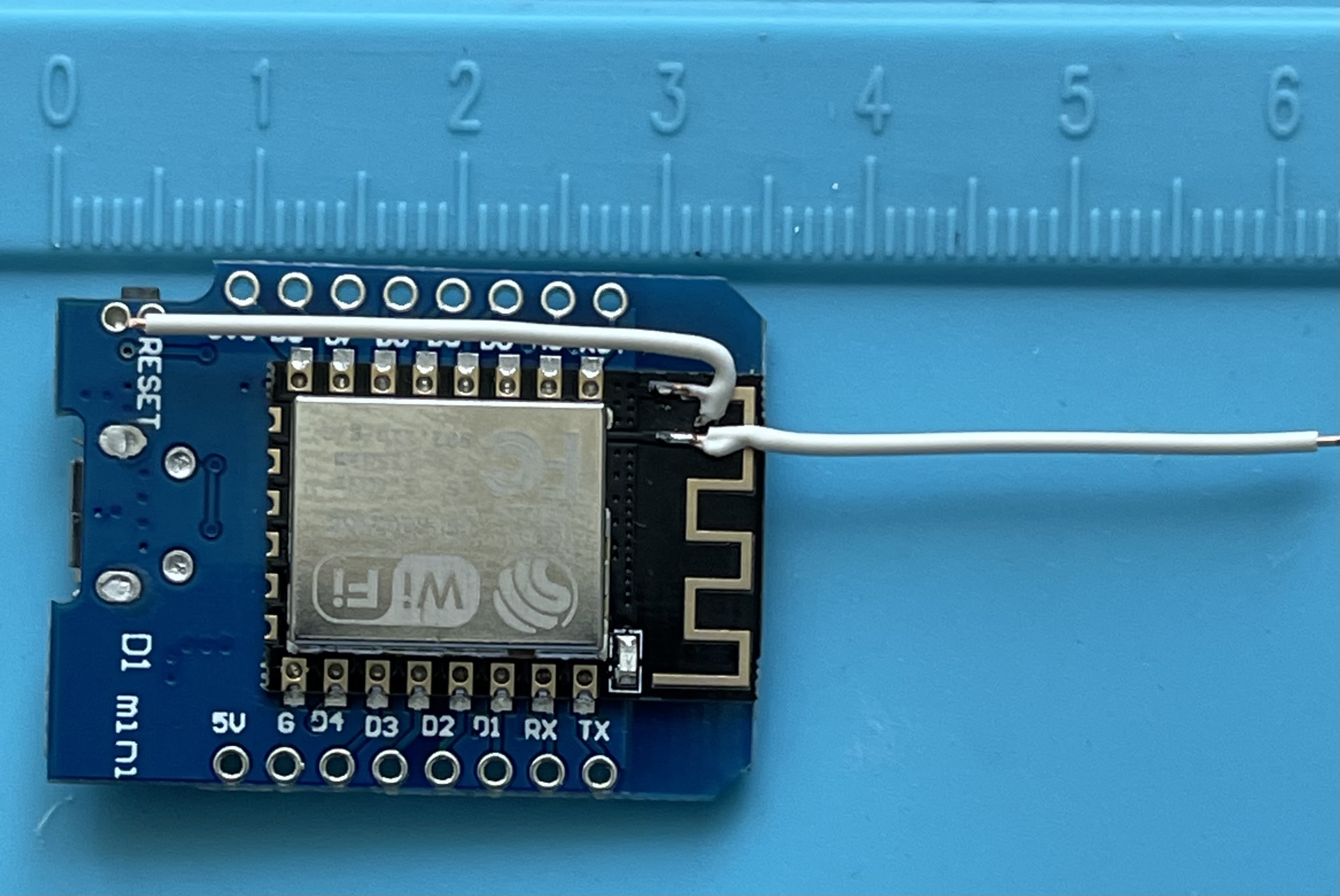
The antenna still works fine, and you can save lot of space in the device design
3 Likes
So, finnaly, my nasty (but working perfect) prototype on the left, and my final design will look like that on the right.

With modified WeMos D1 on one side, power and other electronic in the middle, and RCWL on the other side, in line with dipole.
This is it, the whole story. Hope this clarifies my design in details.
If you decide to follow it, please let me know if you get good results as well.
5 Likes
Thank you @RobertB
This is great now i have something to try this weekend.
if you don’t mind me asking what is the component hanging on the red cable at the RCWl end?
Good to hear it works for you ! But I suspect you haven’t tried the right PIRs then. There’s a surprisingly wide quality gap (more like a huge canyon lol) between garbage like this and industry quality PIR sensors like the ones from Panasonic I linked to earlier. Since I ended up replacing most of my RCWLs with PIRs I have not found a single instance where the RCWLs would have objectively performed better, even during the time they were still functioning properly. In fact, the (quality) PIRs largely outperform the RCWLs in pretty much all situations I installed them in, both indoors and outdoors. And that while using between 170 and 5800 times less power than the RCWLs. The only real advantage of the RCWL is that you can completely hide them, put them behind a wall or in a sealed box, etc.
I’m planning on ordering a couple of 24GHz and 60GHz radar sensors from more reputable industrial part manufacturers and see how that goes and how they compare to both the RCWL and the PIRs.
Edit: nitpicking I know, but the RCWL are not actually doppler radars. They’re not even radars. That’s just marketing. They’re free running oscillators that are detuned by the presence of big bags of water like us. That very simplified principle is their main weakness in terms of reliability and interference with wifi and other RF. Actual radars, like pulsed coherent radars, are not affected by all that.
2 Likes
I see you’ve examined these pictures really carefully!
It’s ferrite bead, from the time I’ve tried to filter power lines. Doesn’t help, but I was too lazy to de solder it back
1 Like
Yes, you are absolutely right
I’ve compared RCWL with PIR’s on the same price tag, so obviously the cheapest ones. I know there are high quality PIR sensors, actually I have quite a lot of them in my commercial security system, working just fine for over 10 years. And I agree with you that this will be probably the best way when you are going to develop high quality security system.
But I’m just using them to automate lights, as you can see on last pictures
So, once I’ve found a way to pair it with ESP8266 (just for curiosity, because RCWL works fine with NRF24L01 radio), I just share my experience
4 Likes
Hi, just some noob question
How do you connect from existing live wire of the ceiling lamp to your wemos d1 safely?
If you tapped in to the ceiling light live wire, that means the light switch need to turned on all the time correct?
Yes, that’s correct. You need to continuously power your controller (via any AC-DC converter, you can see it in the middle), and switch light by relay, SSR or triac (search “arduino relay module”).
Actually for this particular project I’ve used more complex solution - modifying original LED driver with optocoupler and mosfet, but I’ll recommend such an approach for more advanced users only.
I’ve also added LDR to report ambient light level, and custom solution to detect state of wall switch.
And finally nice to say two of this devices

works flawlessly for 8 months for now


4 Likes
I really appreciate your work and sharing your experiences. You saved me hours of trial and error - and ultimately convinced me to skip both PIR and microwave and go to LIDAR.
LIDAR has its own issues too. They’re very fun and I’ve played around quite a bit with various setups around them, but ended up keeping just one. The best and most reliable detectors in my setup are the Panasonic PIRs, by far. They’re the ones I ended up settling on for almost all of my outdoor perimeter detection now and they’re just been working great. You can get them with all kind of different lenses that fit pretty much every use case. The amount of false positives is extremely low (maybe a couple a year), especially when combining two or more sensors in difficult spots.
2 Likes
Thanks for the final analysis - I’m having trouble with false positives with cheap PIRs during the day.
As my last attempt, I used the microwave + PIR, which seemed to work at first, but then started with random false positives.
I’ll give those Panasonic PIRs a try - maybe two of them together with some validation logic.
Also thanks for the tip on the 433Mhz transceiver - I’m not having great luck with Zigbee range.
It has a null aligned with the long axis of the PCB.

So even without the dipole modification this orientation should work:

Also your dipole radiation pattern is going to be badly effected by the ESP shield the way you have it shown bent in that picture.
1 Like
Thanks, I couldn’t find that picture.
Somehow the setup with original antenna generates a lot of problems to many people, no mater of (reasonable) modules distance and position, while that dipole works fine for me for over year now.
That’s the “magic” of RF applications ![]()
Might be something to do with the highly distorted dipole pattern you probably have. That would not radiate very efficently.
@HeyImAlex - First of all thank you so much for sharing all your findings! I recently purchased both the RCWL-0516 and the HFS-DC06 for a project. I wanted to replace an unreliable SmartThings Motion Sensor (they are great indoors but at my front door - outside - it disconnects and the battery drains fast) plus I wanted to add humidity readings as well. I ended up picking the BME280 and the HFS-DC06 as I was concerned about the sensitivity of the RCWL on the back side of the sensor which would be pointing in a direction inside the house where there would be movement. The HFS also had easy delay and sensitivity adjustments.
Long story short, all my tests worked great when testing the sensor with my benchtop power supply, and then perfectly again when using a Wemo d1 8266 ESP… but when I opted to build the sensor with an ESP32 it all went downhill. At first the sensor was suffering from conducted EMI from the VIN (same buck converter powering both) then when I moved everything to a breadboard to test LP filters, I started also having issues with (I suspect) radiated EMI.
I gave up and moved back to the Wemo d1 8266 and it works perfectly…

The BME280 is in modified the cable gland on the right. The conduit connectors on the left will be used to screw this in on the side of the mounting box of an IP Camera. I may need to shorten that a bit. Bonus is that I can easily adjust tilt as I did not glue the conduit inside the two adapters.
This is where I was sharing my findings but I don’t even get close to all the great info you shared!
1 Like
I wish I found this article sooner, I am so grateful for your sharing. After months of successful use with esp8266 and PIRs my set up became unreliable especially on sunny days. So I tried the Panasonic PIRs but that didn’t I prove matters. So I have been experimenting with RCWL-0516. It seemed to work on my desk, but when I installed them at my back door (inside and out) to control a pet flap, it gave very unreliable results. My Esp and PSU are separated from the sensors by about 400mm. I’ve used ferrite beads on the leads. Ironically I found using shielded cable to connect the sensors to the esp gave worse results.
I’m still a novice at electronics, so I would be grateful if someone could advise:-
As I am limited to the number of GPIOs, can I wire a PIR and RCWL-0516 in series, i.e the signal wire of the RCWL going to the VCC line of the PIR?
What code do you implement to filter false alarms, I can see these as very short duration signals using LEDs to monitor the signal state of the sensors.
Many thanks, Paul.
can you tell which exact panasonic model you tried? there are many different models and I don’t know if any of them would work for me. I’m talking about the cheaper models.
I use several different ones, depending on their location.
See this guide. You will want the EKM series (not the AMN). The EKMB sensors are very low power, mostly for battery devices, the EKMC are for powered devices. The EKMC have slightly better detection and false trigger filtering, because they have better signal processing than the EKMB due to power saving constraints for the latter. But in practice it makes very little difference. All remaining options are about the lens. You’ll have to choose according to your use case. Look at the detection patterns, sensitivity, range and possible size or aesthetic considerations in the guide above.
1 Like