Hey everyone!
I had been using ADT for a while, but they were increasing their prices $5 per year. What had started at $35/month was about to become $55 four years later. Thanks much for being a loyal customer…but no thank you, cancelled!
I always have some ESP8266 laying around, so I started playing with the Konnected.io firmware, connected all my wired zones (all wires go in my basement), added some zigbee sensors for a few doors that had ADT’s RF wireless sensors, connected the siren, created some automation, used my Google Homes to announce stuff etc…pretty cool! I was pretty happy about it.
And then it was time to demonstrate and teach my wife on our new alarm protocols…and the biggest questions were…“what about those keypads? Do I really need to do all this from my phone? What if I don’t know where it is? Can’t you find a way to use the keypads?” Challenge accepted!
Got down the google rabbit hole, found some solutions, which seemed quite complicated, what about a tablet? We need a frame, a charger…times 3 (we have 3 floors, one keypad on each), mmm…no.
So I took those keypads apart, and bingo! Let’s just re-use the hardware, but accommodate custom electronics (Arduino Nanos), all connected via serial to an ESP8266!
Step 1:
Cut the tracks on the circuit board to isolate the original electronics from the new one (I just section the track using a blade)
Front:

Back:

Step 2: Widen the holes so that WS2812 pixels can fit (see pic 1 above vs pic 2)
Step 3: Solder all the wires
Step 4: Add the LEDs (6 total, #1,2,3,4 for keypad backlight, 5 for “Armed”, 6 for “Ready”)
Step 5: add the Arduino Nano
And here it is complete!

On the Nano:
- TX1: connected to ESP8266 RX pin (I used the gray wire going to basement). Diode added so that multiple keypad send data to the ESP
- RX0: connected to ESP8266 TX pin (Yellow wire going to basement)
- D2: Keypad column 4
- D3: Keypad column 3
- D4: Keypad column 2
- D5: Keypad column 1
- D6: Keypad Row 4
- D7: Keypad Row 3
- D8: Keypad Row 2
- D9: Keypad Row 1
- D10: Din pin on WS2812 strip
- D11: Buzzer pin
- Vin: 5V coming from basement (red wire)
- GND: GND coming from basement (black wire)
- 5V: To WS2812 strip
- Buzzer and WS2812 strip grounds connected to ground points around the board
The ESP is much simple, all we need is TX, RX, Vin and GND.
Coding…that took some time and is still WIP. But on a concept standpoint:
- All the keypad does is accept 5 digits (4 digit code + action) and sends to ESP
- ESP validates the code, and sends the action to HA via mqtt
- HA receives the mqtt message, sets the alarm panel to the requested mode, and sends the alarm status back to the ESP via mqtt
- The ESP receives the status, sends it to the Arduino Nano on all keypads
- The keypads beeps and LEDs change colors according to status
Features I have implemented and tested working so far:
- Disarmed, armed_home and armed_away modes with different beeps and colors
- Pending, arming, triggered states with different colors and beep patterns
- Chime on/off (keypad will toggle HA switch)
- Chime (keypad beeps when door/window opens if HA’s chime switch is on)
- Ready / not ready lights (green vs orange)
- Timeout: 5 seconds after pushing keypad button
I am on an amateur level when it comes to electronics and coding, any feedback welcome!
Let me know what you all think!
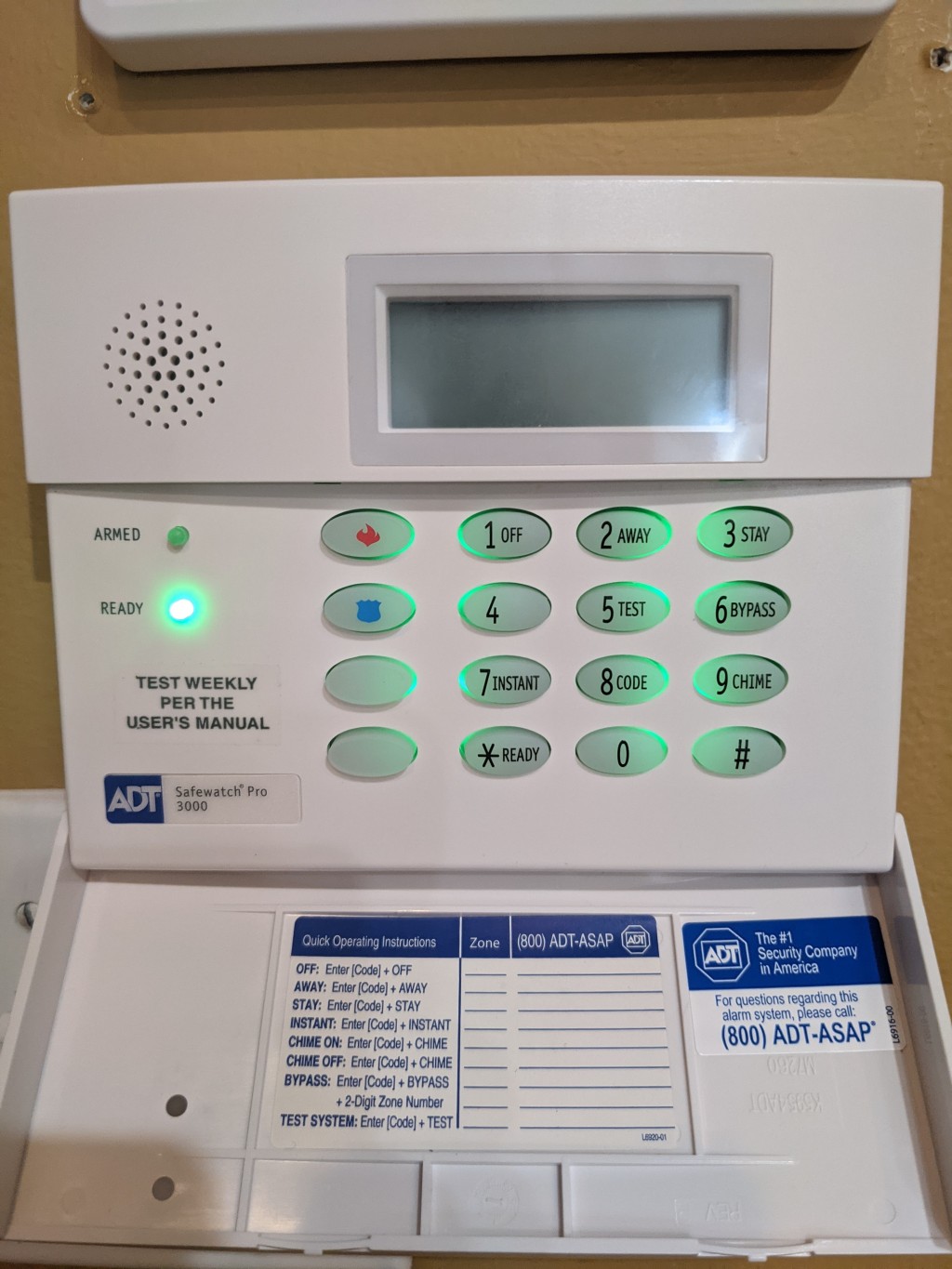
Oh…and here it is on the wall. And yes, I gave up try to reuse the LCD!