Retasking a 2nd Gen Echo

Yes, I used a standalone AMP specifically a MAX98357 which you can see in the photo. Unlike the 2nd gen Echo the 3rd gen echo dot’s DAC/AMP is integrated into the main PCB so I didn’t even attempt to use it.

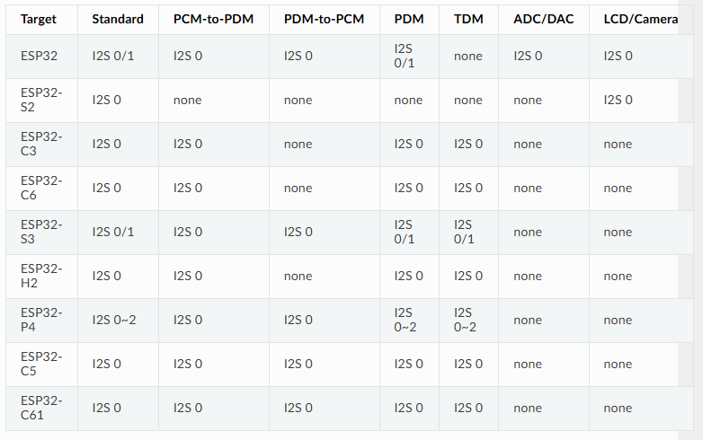
When I was searching for a SBC that could fit, I was having difficulties finding one that could handle 5 I2S streams, I didn’t realize that the ESP32C3 could handle so many I2S channels. I am interested in your PCB however, currently, I am planning to do some form of on-device voice isolation and wake-word detection. I picked up a Luckfox Pico Ultra W which is barely small enough to fit inside the dot with some modifications. It uses the Rockchip RV1106 SOC which has a built in DAC, 8ch I2S and 1 tops NPU. Unfortunately you cannot send I2S to the DAC and on the external pins at the same time.

It might not be worth the effort to get the on-device stuff working but I like the idea of it.

1 Like

Hi,

I’m also uncertain about the benefits of getting the DAC working. It’s possible to purchase a breakout board for the MAX98357 for around €1.60, which, while less elegant than using the onboard DAC, does simplify the wiring/programming.

After conducting some research, I’m convinced that the ESP32-S3 is the ideal choice for our needs. It features 2 I2S channels and offers TDM support. In comparison, the ESP32-C3 has only about 380kB of RAM, whereas the S3 boasts 512kB. Given that the speaker and microphone components in ESPHome are known to consume a substantial amount of RAM, opting for more memory would be advantageous.

Regarding the setup of the MAX98357, how did you configure it? Did you employ another I2S interface, or did you utilize TDM?

2 Likes

Hi,

I (and some others) have been working on trying to repurpose the echo dot 3, and I am currently also looking at interfacing the ESP32-S3 with the mic board. I was wondering if you could share a schematic or wiring that you have as shown in the picture of your setup - I managed to figure out a few things about the boards, but this would surely help a lot.

As a side-note, we did manage to dump the flash of one of the dots and make it mountable images - perhaps there is some configuration or other information in there that is helpful.

Joost

3 Likes

The design is essentially the basic schematic initially introduced by SynAckFin in their first post. However, it incorporates level shifters for the I2S/I2C lines, accommodating the digital core’s maximum voltage requirement of 1.95V. Additionally, a voltage converter is employed to manage the 1.8V, 3.3V, and 3.8V power supplies. To drive the speaker, a cheap I2S amplifier from AliX is utilized. You simply require a breakout board for the ribbon cable, which will grant you access to all the necessary data lines utilized by the MCU on the Dot.

Unfortunately, I haven’t had the chance to adapt the Raspberry Pi script from Prismo for the ESP32 yet, but I hope to tackle it soon. It would be fantastic to utilize the microphone array from the Echo, as all the alternative voice assistants rely on inferior hardware and simple microphones. At the moment, there are no affordable microphone arrays available. Additionally, the casing of the Dot is quite attractive and has a professional appearance.

Hi Hows it going on your project?

I finally was able to get a almost free echo Gen 2 that I have really been wanting to convert into a squeezebox running the Squeeze32-esp firmware. I like that it has the larger midrange speaker + tweeter. I am not an EE and mainly tinker, but have finally taken some time to take apart the unit and thinking of a easy to use design. For my first thought, I would love to reuse almost all of the bottom PCB, which has the power section and amp. I want to focus on the mid level PCB which houses the processor. My thought is to design a drop in replacement that interconnects to the existing base and top PCB flex cables. The drop in pcb would have and ESP32-WOVER, which would feed a PCM5102 I2S DAC (a configuration supported by squuezelite). Then analog down to TPA3118. I would have to figure out how to best plumb in the other controls that can be used on the Squeezelite.
I am working on learning kicad to start laying this out. but since I am new to PCB design, it might take some time.

Before diving in, any thoughts on the practicality and level of effort needed for this? I am hoping others could use it as well to repurpose the Gen 2.

1 Like

Hi,

That sounds like a solid plan. The biggest challenge will be configuring the registers for the TLV320ADC3101 correctly. From a hardware perspective, it’s not overly complicated, but you will need multiple voltage levels (3.8V, 3.3V, and 1.8V).

I would recommend against using the ESP32-WROOM module; the ESP32-S3 seems like a better fit due to its support for TDM, which the TLV devices utilize. However, I’m not entirely certain how critical TDM support is for the ESP32 in this context, but it’s worth considering since the TLV devices communicate using TDM.

For the PCBs, I suggest using JLCPCB for both fabrication and assembly. The connector for the flat ribbon cable can be particularly difficult to solder by hand, and JLCPCB offers very competitive pricing for assembled PCBs. Additionally, there’s a fantastic add-on for KiCad that makes it easy to source parts from JLCPCB.

Hi Chris,

Thanks for the great info! Dumb question, but TDM I am assuming is time division multiplexing. Thanks for the heads up on the S3 for utilizing TDM. I think the connection to the ADCs for the mics was a secondary thought and I had not put much thought into that.

Thanks for the info on JLCPCB. This is a new domain for me and its good to get these tips.

I’ve had some success with this and can now record from 2 of the microphones and fully control the LED ring.

Everything is in a Github Repository including drivers and wiring diagram.

Here is the wiring diagram:

and this is what it looks like wired up!

2 Likes

Awesome work! I’m planning to adapt this for the ESP32 and the Echo Dot 3 soon.

I’m almost finished with the custom PCBs that incorporate an ESP32, designed to replace the power board on the Echo Dot 3.

Does anyone have a pinout for the Echo Dot 3 cable? It would be extremely helpful if there’s an existing pinout available; otherwise, I’ll have to measure the connections myself.

Btw the TXB 0104PWR should work for i2s and 5V to 1V8 logic level shifting. The TXS0104E should be ideal for the i2c logic level shifting. The TXB 0108PWR should probably work for the i2s and the i2c communication though not sure if 2 level shifters are absolutely needed (the TXS series is ideal for open-drain communication like i2c though).

Here’s my schematic. I haven’t adapted it for the Echo Dot 3 yet though.

I plan to use an AliX buck converter module to step down from 5V to 3.8V. For 1V8, I want to use a low-dropout regulator to convert 3.8V to 1.8V. The TPS79318 is perfect for this, as it provides a fixed output of 1.8V. Since the TLV devices consume relatively low power, an LDO should work well in this application. For i2c I’m using the TXB 0108 (AliX moudle) and for i2s I’m using the TXS 0104.
For the Amp I’m using a MAX98357 AliX module, don’t think its worth to use the onboard Alexa Amp.

Feedback would be appreciated.

Hi,

I’ve measured the board to identify the corresponding pins on the connector. Could you please verify if everything looks correct? I’m particularly concerned about the DOUT pin, as it appears unusual. It seems that the mysterious chip UY96D (as discussed in this article: Brian Dorey’s Blog) activates DOUT on the TM28 (which corresponds to Pin 25 on the connector).

Test Point ™ Function Connector Pin
TM7 I2C serial clock 14
TM10 I2C data 16
TM11 3V3 37
TM16 Audio serial data bus word clock (input/output) 21
TM19 Audio serial data bus bit clock (input/output) 23
GND Ground 6
TM62 Enable IS31FL3236- Shut down the chip when pulled low 20
TM13 RESET TLV 12
TM27 IOVDD/DVDD TLV 34
TM28 Probably DOUT but DOUT has no direct connection to the connector only connected over UY96D 25
AVDD Analog supply voltage (probably 3.3V ??) 37 and 29
TM5 1.8V not connected to TVL Chip 28
VDD IS31FL3236 VDD IS31FL3236 (3.8V or 3.3V??) 35

Thanks for the information about the TXB 0104PWR, I’ve ordered a couple and will try them out once they arrive.

On the 2nd Gen DOUT also has no direct connection to the connector. Instead it goes to a chip labelled U101 and marked UY8FE. I assume that this chip is wired with the Privacy LED and disables DOUT when the LED is turned on by driving pin 18 (Gen 2) high. From testing, DOUT stops the moment the LED turns on and starts again once it is turned off.

On the 2nd Gen the IS31FL3236 is powered by 3.8V

On the Audio side you don’t appear to have a Master Clock (MCLK) signal. The TLVs need this if one of them is acting as the bitclock master. The motherboard supplies this on the 2nd Gen and I measured it at 9.6MHz.

Apart from the that the connection list looks OK.

I appreciate you pointing out the MCLK—I completely overlooked it.

Could you let me know how you identified the pins for the volume buttons? I’m having difficulty locating them on the connector. Are they connected to something else in between maybe? They seem to be pulled up and when pressed connect to GND.

I connected any pins I didn’t know the function of to the GPIOs on a Pi and set them all as inputs. Then it was simply a case of pushing a button and seeing which GPIOs changed. Tried it with the inputs pulled up and pulled down.

I checked the MCLK connection, but it appears to be tied to GND. Perhaps it’s not utilized due to the TDM configuration? Do you have any idea why?

Edit:

I guess the Echo Dot 3 uses BCLK for ADC_CLKIN instead of MCLK and generates its own clock using its PLL. In @Prismo script he’s setting the register for this too:

ADC.configure_clockgen("BCLK", "PLL_CLK")

Are you sure the 2nd Gen uses MCLK? On the original pinout you left it unconnected

The 2nd Gen definitely uses MCLK. It only goes to U1 and that acts as the bitclock master with U2, U4 and U5 all acting as slaves.

EDIT:
It goes to U1 via a resistor.

I’m excited about this! I’ve had an Echo 4th gen sitting dormant ever since I started a deep dive down the privacy rabbit hole, and it occurred to me that at the very least I could use the case to house a HA voice assistant (haven’t started down that rabbit hole yet). I’m a pretty capable DIYer but haven’t really done any electronics (yet), so this could be a fun winter project.

Commenting so that I can find it again when the time comes!