I’m currently using an ESP8266 interfacing with an Eno Scientific Well Watch 670 ( Well Watch 670 - Eno Scientific ) to monitor the water level in my well. I’m a beginner with all this so I started off by just using the 0-5v analog output, which works well enough, but the device offers an RS232 output through RX and TX terminals which would be more accurate than the analog output. I am trying to understand how to make this interface.
The device makes a reading every 1s and continuously reports that as plaintext RS232 output, do some light processing on that output, and report it as a sensor/store it. I do not need to transmit any data from ESP->Sensor, only read the continuous output. If I’m understanding correctly, I would want to use the ESPHome logger component with TX: GPIO1, RX: GPIO3, but that’s about as far as I’ve gotten. I’m not sure how to translate this into a sensor entity. Ultimately, my desire is for it to get the readings into InfluxDB as my current analog sensor integration does.
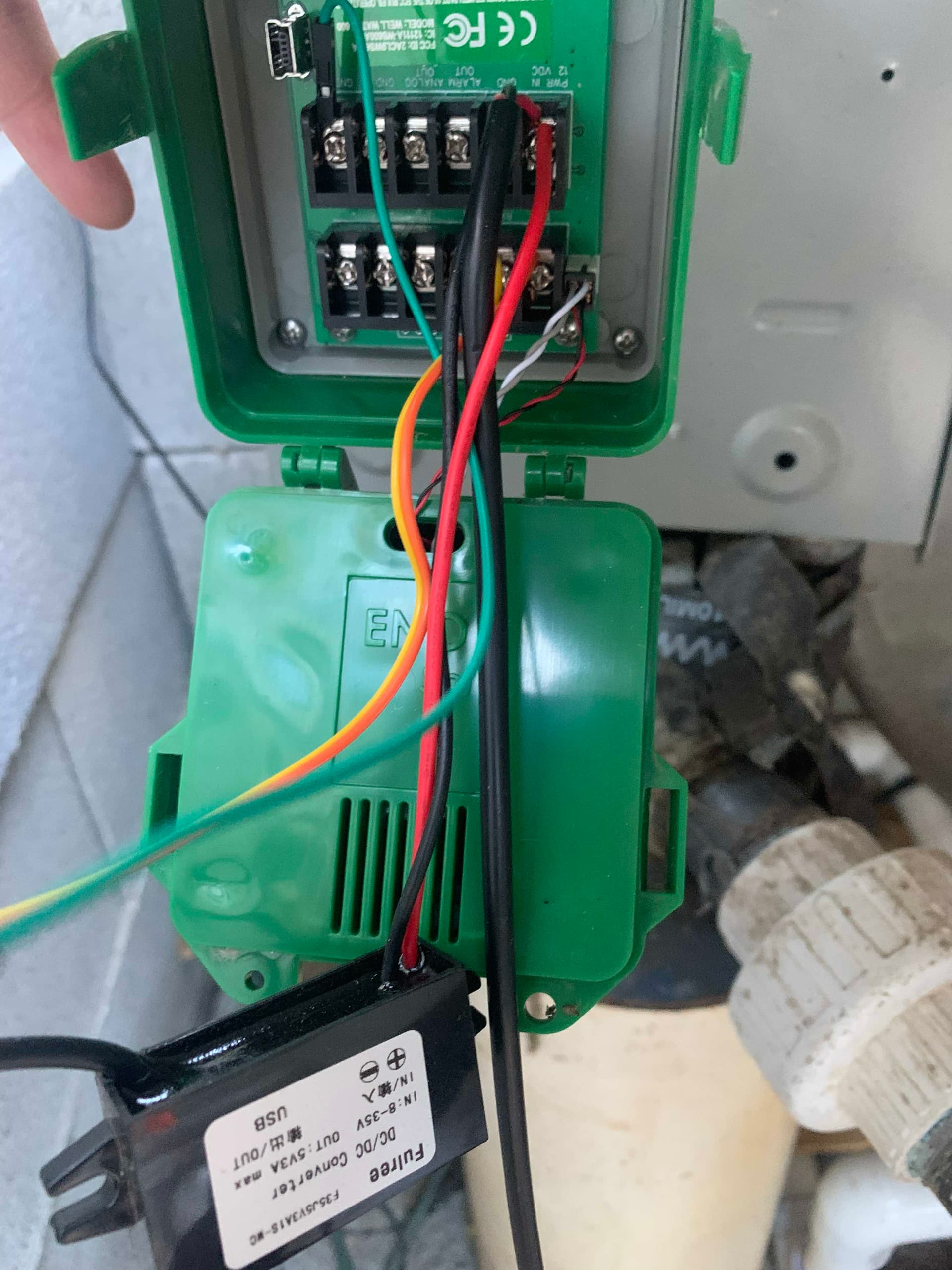
One thing you need to know is that the RS232 output of the WW670 is higher voltage than the TTL interface of the ESP8266. So you will need something like this to convert between the two:
Many similar chips exist but this is the one I used and it worked well for me. I connected GPIO1, GPIO3, GND, and 3V3 from the ESP8266 to one side of this board and the other side to RS232 TX, RX, and GND on the WW670. Be careful to connect the Tx from one device to the Rx on the other and vice versa. If it doesn’t work the first time, this is probably why. I set the WW670 RS232 output setting to “Depth only” but if you want you can transmit more data, you’ll just have to parse it on the other end.
Here’s what I used for the ESPHome code, adapted from the link above in @nickrout 's post. You can remove the debug part after you get it all set up, but that will allow you to verify that it’s working in the logs.
Thank you for posting this. I bought a Well Watch and was happy to see someone had success integrating it into Home Assistant. This is my first experience with ESPHome and working with these small devices. I believe that I have everything wired up and configured correctly but things aren’t working.
I’m having a difficult time debugging. The EPS board (Wemos Lolin D32) is also configured with a sensor for the wifi signal strength and that is working as expected. I mostly get nothing from the RS232 accept for the occasional log message, so occasional that I can’t even get one now to paste it here. Something like << /EF maybe? That is all and that seemed to have more to do with me wiggling wires than anything else.
It has 1 less than glowing review. How do I know if it is working? The led indicating power is on, but I don’t see any activity of the Tx or Rx leds. Should those be lighting up?
Turned out that everything was just fine. I was on the wrong set of pins at one time, then when I was on the correct set of pins I had them reversed. Works great but I need to find a more permanent way to mount things and get an outlet installed near the pump.