Hello All
I was following this great guide on how to implement servo into hassio using ESPhome. I was successful, however i have 2 problems:
- Servo is supposed to be able to do full rotation ,however am not able to get more then ~40° . Is there a way how to extend the movement limits? If I follow official servo documentation on esphome ,maybe min_level / max_level? however is not working , and also considering I am later using the write action to put number between 0 and 100 into it, it is overwritten anyway nope? Here is my config in esphome:
#servo
api:
  services:
    - service: control_servo
      variables:
        level: float
      then:
        - servo.write:
            id: my_servo
            level: !lambda 'return level / 100.0;'
servo:
  - id: my_servo
    output: servo_output
output:
  - platform: ledc
    pin: GPIO19
    id: servo_output
    frequency: 50 Hz
I am sure that servo is capable of full movemement, i have tried with other device
- Servo keep “disconnecting” after few hours. I start esp32, servo works, am able to control it from hassio using input number and write.action. in UI i see the slider being updated same way as servo moves (if we dont consider the problem no 1). After few hours it just stops working. Nothing in logs. Then i just restart ESP32 and all start to work for few hours again…
Any help is much appreciated.
Thank you
Maybe this was obvious to someone , but anyway → Regarding the problem no2 i have discovered that there is no constant voltage in data pin ,even when i try to move the servo. If i restart the ESP32 there is voltage change for every step.
Sounds like you arent using a big enough PSU. Are you powering the servo from the esp? What servo? Is it 5v or a 6-8v servo?
The code is pretty basic and if the servo is capable of 180 or more, it should be spinning more than 40deg.
Ive had horrible results buying servos FYI. Ive received a lot of junk or servos with stripped gears from the start.
Are you sure this servo is indeed good?
EDIT: posting one more time as there was some problem with previos post
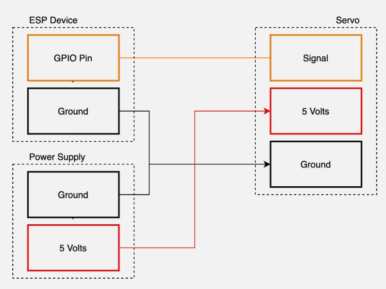
hello . Yes I am using external 5V 3,5A power source following the schema below. The Servo is MG996R so its 4.8 - 6.6v . I can not really judge if the servo is good or bad, i just know that with previous controller it worked, it was connected for weeks without problem. Unfortunately i cant connect the previous device anymore.
I still suspect the problem with disconnecting is somewhere in ESP32, as the volage in DATA is just static after few hours, even when i trigger a change
Speaking about voltage - do you think is normal that max voltage I can get through DATA is 3V ? I already tried to play bit with min_value and max_value from documentation . There is a change, for example if i set the max_value to 30.i can not send from hassio bigger number than 25 for some reason. So there is slight change, but not the right direction. I would expect that this setting is exactly what i am looking for, to set the min and max positions of servo, but not 
Without more details, anyone trying to help you would just be guessing.
You didnt post all of your code that deals with the servo. Where is the number entity? Is it through esphome or HA? If its through HA wheres your automation?
Have you tried manually doing a servo.write: 100%/-100% ?
See if the problem is between HA and the esp, by removing HA from the equation… process of elimination.
No one knows why its its disconnecting every hour or so because you decided we didnt need to see the full config or any logs for some reason. Disconnects are overwhelmingly caused by PSU issues but, they usually reboot automatically and dont need a manual reboot.
Did you try changing it with another PSU? Esp boards are sensitive to unstable voltages and will disconnect. Just because a PSU is working for some random 5v device, it doesnt automatically mean its good enough to be used with an esp32.
Where is it disconnecting from?? From HA? ESPhome dashboard? Wifi? All of the above? This will be a big clue to whats causing it.
Which board is this? And dont just say an esp32.
hello
Regarding the servo movement problem (lets just abstract from the disconnects now). I have made a setup where i abstract from any HomeAssistant variables, am just using ESPHome and set the servo.write action on ESP32 bootup, but still does only the 40° rotation
I have already tried different servo (SG90) and also 2 different ESP32 boards (ESP32 DEVKIT V1 CP2102 & ESP32 DEVKIT CH340). Sorry, but know i can easily tell what type is the “original” third one one as its already mounted and is non trivial to remove it.
Also i have tried it without external powersource and also using only ESP32 pins. I was playing with variables for min/max/idle_level which “does something” but its non-deterministic. Using this method i was able to see that the servo is capable of larger movement the 40° , but still i can not use as its non-deterministic.
this is the ESPHome code
esphome:
  name: esphome-web-8f2fcc
  friendly_name: esp32-test
  on_boot:
    then:
      - servo.write:
          id: test_servo
          level: 100%
      - delay: 2s
      - servo.write:
         id: test_servo
         level: 50%
      - delay: 2s
      - servo.write:
          id: test_servo
          level: 35%
      - delay: 2s
      - servo.write:
         id: test_servo
         level: 0%
      - delay: 2s
      - servo.write:
          id: test_servo
          level: -50%
      - servo.write:
          id: test_servo
          level: -100%

esp32:
  board: esp32dev
  framework:
    type: arduino

# Enable logging
logger:

# Enable Home Assistant API
api:
  encryption:
    key: "hDddCCRskN+K0hUD6lRZafCmzRCmuBvI4iDmySnqG+4="

ota:


wifi:
  ssid: !secret wifi_ssid
  password: !secret wifi_password

  # Enable fallback hotspot (captive portal) in case wifi connection fails
  ap:
    ssid: "Esphome-Web-8F2Fcc"
    password: "37DZJY8XZMcW"

captive_portal:

output:
  - platform: ledc
    pin: GPIO19
    id: test_servo_output
    frequency: 50hz

servo:
  - id: test_servo
    output: test_servo_output
 #   max_level: 50%
 #   min_level: 25%
 #   idle_level: 40%

switch:
  - platform: restart
    name: "testESPrestart"
I have a feeling there is some general problem in ESPhome Servo component . I have found similar issue here , which i will later try to implement. basically it says → Create a Custom Component in C++ in our ESPHome that is responsible for executing the servo’s operating code, and call it from the yaml when we need it.
How to do this is currently above my knowledge and i will need to investigate,
In any case, i am using diffrent boards/ servos / PSU and I still have the problem. It is interessting that no one else (but the one post) have the same problem as i do…
That post is old and there’s no reason you need a custom servo component here.
post a picture of how you have this wired too. You do have your grounds connected right?
Just some words of wisdom for you. Whenever you’re setting up some device or sensor, whatever. Before you add a bunch of configurations, on_boot automations, set up HA services, whatever. First thing you need to do is just make sure the thing works! Just do a bare bones servo configuration. Set up the Servo, set up the Output and in this case for a servo, make some template buttons or something that you can control the movement and then test it.
When you set up all this other stuff and configure 'Optional" settings that you don’t need to do yet and on_boot automations or API services. You’re just adding more potential sources that you now have to troubleshoot through. Now you don’t know. Is it the actual servo or is it code related or your API service or maybe the on_boot that is the problem? You’ve added more possibilities that could be the problem. Always do all this other stuff later on when you know the device is working correctly. If you know the device works first and then add your extra automations and what not and it doesn’t work after that, well now you know the problem isn’t the actual servo because you checked that first and it must be the code you just added. It just makes things easier on yourself for when problems do come up. You have less things to cause a problem and less things that could be the problem if one comes up.
Try this code and only this code(for the servo). Remove or copy/paste your config somewhere else. Lets see if we can get the servo to work with it’s full range with just a bare bones servo config. If all goes well then we can move on and start adding your automations and stuff back to it.
FYI. your ‘Restart Switch’ at the bottom. You really want that to be a button. A switch entity stays On when you push Restart, a Button wont do that. You want the restart switch to just turn on quickly and then turn off. You can do a switch if you really want or you just like how a switch looks in HA but, I’d at least add an on_turn_on automation to do a quick delay and then turn it off.
So basically, You’ve just got a Number entity to pick how much you want the servo to move. Start with something small like just 10 or 20 and then there are 2 buttons. They take the number from the Number entity and then each time you press one of the buttons it will increment or decrement the servo(clockwise/counter CW). This pretty much is what I use to move my pan/tilt camera mount I made, so I know it works fine. Try it out and LMK what happens.

switch:
  - platform: restart
    name: "testESPrestart"
    on_turn_on:
      then:
        - delay: 250ms
        - switch.turn_0ff: testESPrestart

servo:
  - id: test_servo
    output: test_servo_output
    auto_detach_time: 3s
    transition_length: 2s


output:
  - platform: ledc
    id: test_servo_output
    pin: GPIO19
    frequency: 50 Hz


number:
  - platform: template
    name: 'Test Servo '
    id: test_servo_number
    min_value: -100
    initial_value: 0
    max_value: 100
    step: 10
    optimistic: true
    set_action:
      then:
        - servo.write:
            id: test_servo
            level: !lambda 'return x / 100.0;'

button:
  - platform: template
    name: 'Servo Right'
    id: move_right
    on_press:
      - number.increment:
         id: test_servo_number
         cycle: false


  - platform: template
    name: 'Servo Left'
    id: move_left
    on_press:
      - number.decrement:
         id: test_servo_number
         cycle: false
You are right with firstly testing just the basics before doing other stuff. I was only following the post and believing that everything will work. And i need to say that eventually even everything in the post is right as i tested it in other device one more time. But lets start with your test as thanks to that i was probably able to find the root cause.
In a nutshell - the code you provided works and i am able to do almost 180 degrees with the Servo. Thanks for that peace of code, i can use also in the future as its much more convenient comparing to trying to the full circle of servo.write on boot. (Speaking about the testing method on boot, this is anyway not right ,because somehow am not able to get the 180°, nevermind…)
This test was done with TEST testing device (not the one mounted on the wall) and i realize that eventually you were right at the beginning - there will be something wrong my setup from HW point of view which i need to investigate later. Reasoning behind this is that i was measuring voltage between DATA and GND as i was moving with slider in both devices (lets call them TEST and END for the one which is mounted on the wall).
- on TEST device there 0V when no-movement and 0 - 0.38V when moving -100 / + 100
- on END device there is voltage always present . 2V - 3V when moving -100 / +100. This means when servo is fully open +100% ,there is constant voltage ~3V from DATA pin. Which i guess is wrong. FYI i have already tried 2 different PSU for the servo with END device, same result
As i said, i will need to investigate later, but if you are interested feel free to take a look into the ESPhome config of END device, photo of END device placement and basic wiring diagram (sorry its terrible i know)
To the END Device I have connected devices:
- servo MG996R
- 1 relay module
- active piezobuzzer
- temparuture meter dallas 18b20 (which actually is 3V, so maybe there from i have the voltage if i did something wrong)
The complete code
esphome:
  name: "esp32-krb"
  platform: ESP32
  board: esp32dev
# Enable logging
logger:

# Enable Home Assistant API
#servo
api:
  services:
    - service: control_servo
      variables:
        level: float
      then:
        - servo.write:
            id: my_servo
            level: !lambda 'return level / 100.0;'
ota:
  password: "877f4fdd41703c8d3e46232eda9bf5e0"

wifi:
  ssid: "XXX"
  password: "XXX"

  # Enable fallback hotspot (captive portal) in case wifi connection fails
  ap:
    ssid: "Esp32-Voda Fallback Hotspot"
    password: "XXX"
#temp
dallas:
  - pin: 18
    update_interval: 5s

captive_portal:
#servo
servo:
  - id: my_servo
    output: servo_output


#servo a buzzer
output:
  - platform: ledc
    pin: GPIO19
    id: servo_output
    frequency: 50 Hz
  - platform: ledc
    pin: GPIO26
    id: buzzer_output

#temp
sensor:
  - platform: dallas
    address: 0xcb0000000f4e2628
    name: "Teplota Krb Dnu"

#rele a buzzer.
switch:
  - platform: gpio
    name: "Krb Cerpadlo Rele"
    pin: 27
   # restore_mode: RESTORE_DEFAULT_ON
    inverted: true
  - platform: template
    name: "krb_switch_buzzer_virtual"
   # inverted: true
    optimistic: true
    turn_on_action:
      - output.turn_on: buzzer_output
      - output.ledc.set_frequency:
          id: buzzer_output
          frequency: "2441Hz"
      - output.set_level:
          id: buzzer_output
          level: "50%"
    turn_off_action:
      - output.turn_off: buzzer_output
  - platform: restart
    name: "Krb ESP32 Device Restart"
In any case, thank you very much, you had been already very helpful.
awesome! I knew it would work, IDK what that post was about creating a custom servo component because i’ve made several servo projects and had no issues, well no issues once I figured out what i was doing for the most part.
I meant to bring up that on_boot section with you too. I wouldn’t recommend doing it like that if you need an on_boot automation. Put that automation inside a script and then call the script in from the on_boot: Setting a Priority and the right priority(not too soon). Those were 2 issues I recall off the top of my head.
I also meant to mention measuring the voltage last time too. That Data line has a PWM signal going through it when the servo is active. PWM is a modulated voltage and you can’t really measure it with a multi-meter and the measurement you are seeing, it isnt really useful information that can tell you something. So, at 50Hz that voltage is modulated 50 On/Off cycles a second and you wont get accurate voltage readings trying to measure that.
It’s hard to tell what you got going on in that box. The only things I can make out are the relay and the esp32. It may be a little messy but you get an B from me. You’re taking electricity and electrical fires seriously by using good connectors and some wire ferrules. You’re also using an actual project case too. I’ve seriously seen people hot glue a breadboard on their wall with wires going all over the place and I said, “WTF! are you serious? You trying to burn your damn house down?”
What exactly are you making anyway? Is that green/black thing some sort of pump?
I’ll go through the code if you have a problem with it. I don’t go around reading code for fun, i’m not that lame.
If i can make another suggestion. Since soldering wires to gpio pins isnt the best idea and breadboard wires come loose easily or break off. The other thing is if that box gets kicked or falls and the relay or something else bounces around in there, POOF! I highly recommend these breakout boards. Your wires are secure and they have holes for mounting the board so its secure. You can get them for the fat es32 like you have, they have them for the skinny esp32, and the esp8266 nodeMCU, Pico’s.
You’ll like them, i know i do.
thanks for the B, much appreciated  i have tried to design it best and safest way possible. Btw starting next month I start to attend electrician training so the things might get better. For now i was “lucky” with my work, and following my best knowledge, nothing wrong happened in my house. But for future i want to know more, understand not only how to connect things, but understand how they fundamentally work.
This actually brings me to the root cause of the problem. Eventually i figured out what causes the problem. Starting testing with the most basic config with only servo included (which worked also on END device) i was adding devices one by one. In the moment i have added buzzer to the setup → servo movement was again malfunctioning .
My suspicion is that it has to do something with the fact, that both servo and buzzer are using PWM output
output:
  - platform: ledc
    pin: GPIO19
    id: servo_output
    frequency: 50 Hz
  - platform: ledc
    pin: GPIO26
    id: buzzer_output
switch:
  - platform: template
    name: "krb_switch_buzzer_virtual"
    optimistic: true
    turn_on_action:
      - output.turn_on: buzzer_output
      - output.ledc.set_frequency:
          id: buzzer_output
          frequency: "2441Hz"
      - output.set_level:
          id: buzzer_output
          level: "50%"
    turn_off_action:
      - output.turn_off: buzzer_output
I have found some similar posts online, which suggest to use different, but did not work for me.
BUT there is one good news - i figured out why the servo was disconnecting thanks to this discovery - When I was testing the buzzer and at the exact moment also the servo, servo “disconnected” . I guess its exactly both of the outputs are PWM ,but having different frequency. And obviusly i figured this out also thanks to you - i would never be able to figure this out
one more thing i have noticed → if I add 'freqeuncy: 50hz' also to 'buzzer_output' the servo works normally , until i first test the buzzer.
Any suggestion?
I mean, i could “live” without the buzzer, it serves “only” as an alarm when temperature is more then 90 degrees, but its nice safety feature (worst case scenario i could add this alarm to some other device outside of END device).
To give you context about the use-case → i use this END device as fireplace regulator.
- Basic use-case is that it turns on water pump if temp > 30 degrees and turns it off if < 30 (thats the relay for). And i have that type of fireplace which is heating water also in my radiators
- Together with i have installed a air damper below the fireplace which controls airflow based on the temperature. this is not a must, the fireplace can operate also without this, but it optimize the wood burning
- the temperature sensor is located directly “in” fireplace
- the ttgo displays show some values like temperature, damper level, relay on/off…just a display
- i am also trying to implement safety features like
- i have external 220v switch which allows me to turn on the heat pump manually in case something wrong with END Device or Hassio
- i have installed also other temperature meter on the way, to make sure i always read the real value (in case something happens to thermometer in fireplace)
- buzzer as an alarm if the water temperature is too high
It might sound like I am giving too much hope that everything will work fine with my setup, but comparing to my previous setup installed before (on/off 220 switch and temperature meter with display only) i consider this still to be safer than it was .
Attaching pic of the my ESP32 DEVKIT1 Pinout
Thanks for the tip for breadboard. For now i am using this dupont line cables with connectors made exactly for pins and works also well
EDIT: you are right , for the buzzer it would make sense as i had to solder that one

Nice! Maybe its just because ive got older and (arguably) wiser(38), i would love to keep getting education. Its really kind of miserable when you dont enjoy the work you do for a living and then you have hobbies youd love to get paid to do but, your not qualified. Live and learn i guess. On the bright side, i may be coming to for help later on!
I always forget about multiple pwm devices on a single esp32. You’re right, it does cause problems and more so if theyre using different frequencies which is probably why messing with the frequency seemed to help.
In the ledc Docs, its under ‘channel’ and it kind of explains a little about it. If you dont manually put the 2 devices on opposite channels, look at the frequency config in the Docs. The default frequency is 1000Hz while your servo is set for 50Hz and something else is at 1000… Hz is a unit or (1 cycle per second) so it specifies the timing basically and 50 isnt close to 1000, right. You should be fine just manually assign each ledc its own channel then its perfectly fine if one channel is 500 or whatever and the other is 50, thats no problem.
I would say ditch the buzzer but, im just bias. Every buzzer ive ever tried has been garbage and you can barely hear them unless your less than 5’ away and in a quiet room.
Ive got a wood burning stove i use to heat my garage/barn and always thought about doing similar things but damn if there isnt enough hours in the day!
I do have a “control box” i made and part of it is a relay that turns on the exhaust fan in the wood stove. No big deal but, youve got me thinking about it again.
That many sensors/devices is a respectable project. Its nowhere near being too much for an esp32 to handle so you should be just fine. You know the esp32 has an internal temperature sensor too, right?
Its not the best way to monitor temp in a closed box due to the heat the esp32 alone generates but, with a little calibration it works pretty good if your in a pinch or as a backup sensor.
I mean, you can use them just be aware they arent very durable. The female ends wear down over time and they fit loose/sloppy which causes them to be easily disconnected. The male end, that metal pin breaks off easily and if it doesnt get stuck in a female header then its a little piece of metal that will wreak havoc if it contacts the esp board and causes random short circuits.
They do have anothe type of breakoit boards that have a blank pcb area in the middle so you can solder on your own sensors or extra circuits you may want to build. I only recall seeing them for esp8266 NodeMCU though. Thats my goto board though so i may not have noticed them for esp32’s
You can make an ezp32 fit in the esp8266 breakout boards if your in a pinch. The pin labels wont match obviously but its an option FYI.
Eureka !
Thank You very much for this remote debugging session @Fallingaway24 , i surely would not be able to make it work without your large contribution.
This means, that everything works as supposed + i have learned lot of new stuff which is always great. Personally its strange for me, that you when you setup different frequency ,you need to setup also different channel, I guess this is always desired…anyway now i know what to do
I was not aware of the internal temperature sensor, quickly checked in doucmentation and implemented - however i have the device which reports faulty value, but still might work on some other one ( i already have my summer ESP32 project in my mind considering some pool automation ) So thanks for this as well.
I wish you good luck on your project as well, but I guess you dont need luck, cause you surely know what you do. Therefore i rather wish you time for you project.
Thank you once again
All the best
Rado
You have to use different channels AND 2 channels not adjacent to each other. I explained this once and it explains it in the Docs that i keep repeating you gotta read, its really not optional, theres important information in there.
Frequency is essentially the same as timing. If you have 2 pwm outputs that use different timing or if a music metaphor makes more sense, you could say “beats per second” a single channel can only do (X beats per second) so you have a servo that needs 50Hz (50 beats per second) and you also have a buzzer youve set at 2441Hz or 2,441 beats per second. Each pwm channel has a little hardware timer in there and it cant do 50BPS and 2,441BPS at the same time. It can only do 50 or 2,441.
So, when you seperate them onto different channels, that each have their own little timer, then its no problem. Channel 1 is rocking at 50 beats and channel 3 is doing some funky techno at 2,441 beats.
Yes thats understandable. I am just saying that this /could be done automatically internally within the esp32, as I am setting different frequencies. Meaning that it’s kinda duplicate to set also the frequency and chanell as well. Cause the 2 different frequencies don’t work without setting 2 different channels anyway
Ya, i kind of agree with that but, i also understand the desire to keep as much as possible in the hands of the person using the board. Its alot easier to add channel: 2
than it is to circumvent some automatic channel assignments done behind the scenes because the software thinks it needs to put up guardrails and dictate what you can or cannot do.


