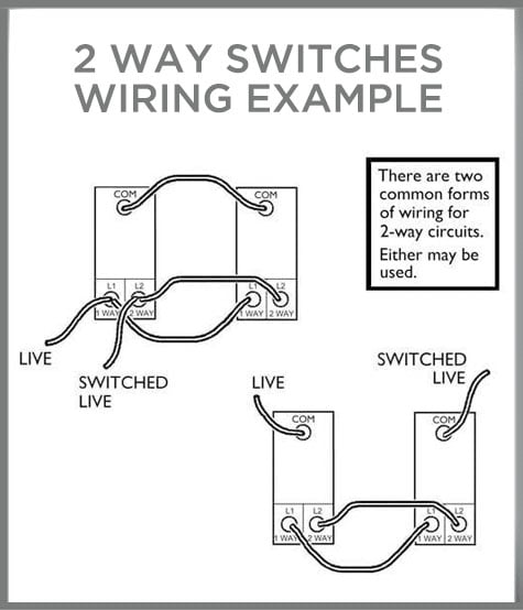
I want to install a Shelly 1L in my hallway which has two lights both controlled by two switches. As far as I can tell, there are two ways that two-way switching can my done. My situation is the one on the right in this diagram (one switch with permanent live, other with switched live wired to common). https://www.downlights.co.uk/media/FAQs/wiring-example-2-way-switches.jpg
I’ve searched for hours trying to get my head around how to wire the Shelly in and I’m pretty sure my answer lies in this diagram from the Shelly Facebook Support Group: Log into Facebook | Facebook
I’m a competent amateur electronics hobbyist so I understand the basics. But Perhaps I’ve been looking at wiring diagrams for too long cause I just can’t work out what goes where.
Can anyone in simple terms explain what I need to do to get from where I am now to having the Shelly in place?
I’ve had my fair share of confusion about this too (and I have a degree in engineering (not practicing), but I’m not an electrician). I too have a 2-way hallway switch that need to be made smart at some point. Care to share what you went with? The FB diagram? First or second one?
The confusing part for me was that the second switch requires moving L2 to Common which seemed counterintuitive to me. But in this two-way wiring setup it does make sense.
To clarify the steps (which in some ways is much easier to comprehend than interpreting the diagram):
Switch 1 (with permanent live)
Disconnect permanent live from common and connect to L of the Shelly 1L
Connect a jumper wire from O on the Shelly to L1 on the switch (note leave the existing L1 wire in place)
Disconnect L2 from the switch and connect to SW1 on the Shelly
Connect a jumper wire from SW2 on the Shelly to Common on the switch
Switch 2 (with switched live)
Disconnect L2 and connect it to Common (note you should check that L2 is actually L2 on both switches. In my case they were the same colour which makes sense.)
Note - leave the common in place so you have two wires connected.
Finally, when configuring the Shelly, make sure you have both Switches in Edge mode.
Glad to finally have this up and running in my hall and hope this method helps some people. I have a little bit of flickering even after installing the bypass, but I believe the bulbs play a part in this too. The actual install is spot on and as far as the wife is concerned, the switches are the same as they’ve always been! Winner.
On Switch 2 I initially removed the common wire and blanked it, and when reread the instructions I realised I should have left it in place.
Also discovered L1 and L2 were swapped (hard to test continuity from a different floor) but again, a quick swap got it up and running.
Excellent. Glad it helped someone as it took me months of investigation before I took the plunge to try the install! I’ve edited the instructions now to clarify common on switch 2 should stay where it is.
Looping back in to say ‘thank you’ for sharing your solution and detailed notes, @fenty17. Can confirm that approach is working great with my hall lights.
Experienced some mild flickering when the circuited switches on. At first I’d assumed it was a wiring issue but have since resolved by changing the Shelly ECO MODE setting to disabled.
Thanks again!
Thank you for sharing the solution. @fenty17 one clarifying question.
In the before picture L1 and L2 are connected to each other. In the instructions on permanent live side there is a step to connect L2 to SW1 in the Shelly. In the after picture SW1 of shelly is connected to L1 on the switched live side. Is there some kind of mix up between L1 and L2 (In picture L1 and L2 on the permanent live side change sides between before and after picture) or did I misunderstand something?
Now when i trun off one of light switch, shelly is’not possible to turn on light and in this solution if i turn light on via shelly it’s not possible to turn light off via any switches…
You are right that the numbering is mixed up between the images (not my image!). I think you can just assume the before image has 1 & 2 the other way round. The point is they are connected to 1 & 2 respectively on the second switch before you start. I imagine the person who made the image ordered them this way to avoid lines crossing each other in the diagram.
Whichever side you move to connect to ‘O’ on the Shelly, it’s the other side that should be connected to SW1 on the Shelly.
@petrklic16 - this post is specifically about 2-way wiring for the Shelly 1L. NOT the Shelly 1 or 1 plus.
I don’t have a Shelly 1 but my understanding would be that there are significant differences to how you would wire it up for this situation compared to the 1L.
I’ve been trying to solve this one in my house for a while. Seem whoever wired this house wired all the three way circuits the same way with supply at one switch and the load at the other. So this looks like hte answer I’ve been searching for. …but I am curious why the neutral is not connected to the Shelly in the ‘after’ diagram. What am I missing?
I’m not sure it’s technically a neutral, but I think the answer is that the after has the switched live connected to common on switch 2, L1 on switch 1, AND the O terminal on the Shelly. I’m no expert though. Literally spent days looking at that diagram before I understood what to do! Hope it helps you.
Most of that makes sense to me, but I guess without seeing what the 1L is doing on the inside it’s a guess. In looking at this there has to be a small current flowing through the load all the time to power the Shelly. Thanks
Thats amazing! Looking forward to trying this. Would there be an issue if I tried this with a ZBMini-L?
They are like the shelly 1L, but with Zigbee instead of Wifi.
Dear fenty17, your solution helped me in a 2 way installation in my home but i have a question though to you or anyone else.
I have in the light fixture 2 Shelly E14 RGB Bulbs and working fine with this way but i want to find a way to make the Shelly1L as Detached Switch to control the lights with HA. In all my other switched (who are not 2 way i achieve that).
With this diagram, the 1st switch that has the Shelly 1L in Detached mode, gets the command fine from the switch, HA sees that and control the lights but the 2nd switch cuts the power to the lights…
Bottom line i need somehow both switches to give the command to shelly 1L but to not cut the power to the fixture and i am stuck a bit atm.
Was wondering if it’s possible to ditch the original switches (two gang switch but one of the switch is 2 way).
Can I connect the com and 1 with a wago connector then with a new smart switch, have one of the switches just be a scene switch that toggles the Shelly 1L?
first of thank you for finally having a proper guide on that, but I have an issue with my instalation, everything seems to be working properly, switching between switch as well with shelly, but when it is off, then it push still little bit of power and the light is blinking/way less glowing. so it is not off. When I turn it on it works as expected.
only possition when it is off is on switch 2 when it is in cable 2 (unplugged wire)
As far as I understand, the Shelly 1L needs the trickle of power to power itself. Two ways to resolve the flickering would be adding a Shelly Bypass to the ceiling rose, or swapping your bulbs out for slightly higher wattage (total of 20W should do it).


