Shelly fan control, or Why my bathroom light switch now has two IP addresses…

In our bathrooms, we had traditional extractor fans controlled by the pull-cord light switch, with a timer so that the fan turned off a little while after the light. ‘A little while’, we realised, was perhaps a bit long in our case, after one guest hinted that the sound of the fan in their ensuite had kept them awake for 20 mins…

The trouble was that adjusting the timer meant getting a ladder and going up into the attic with a torch, clambering over rafters to the farthest, most inaccessible corner, then burrowing through thick layers of fibreglass insulation to get to the fan, unscrewing the top and inserting a small screwdriver in a slot and turning it a little bit. Then climbing back down, going to the bathroom, turning on and off the light and waiting for 10-15 mins with a stopwatch to see whether I’d set it correctly. Then repeating the process until I got it right. Oh, and did I say that we had three bathrooms like this? There had to be a better way.

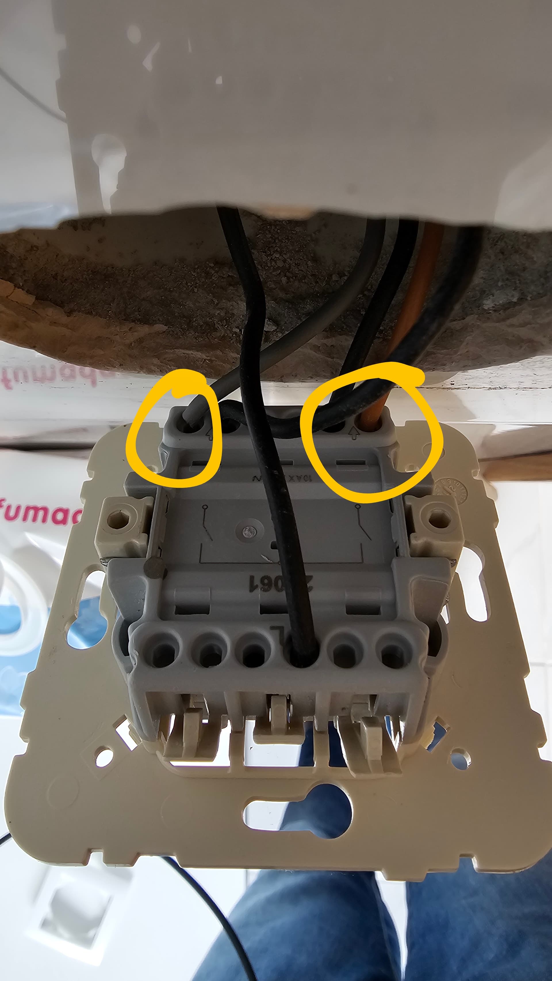
Once I discovered the Shelly 1, with its mains-voltage input, I realised I could use it to read the state of the light switch and control the fan directly, with adjustments being made in software, which would be much nicer and wouldn’t involve inhaling any glass fibres. Even better, I could follow the model that some newer timed fans now use: after the light switches on, don’t start the fan for a minute or two, in case this is just a brief visit. And then, if you’re staying a bit longer, turn the fan on and leave it running for five minutes after you’ve departed. I could also adjust those times if, say, it was the middle of the night.

Once I started to connect things up, though, I realised I’d have to do a bit of rewiring of the lights, too, because of the way things were connected. So I decided to install a second Shelly to control the lights, which meant I could do things in future like turn them on using a motion sensor, or not turn them on if the room was already bright enough, and I could do so independent of the fan and its timing.

Anyway, to cut a long story short, this all worked beautifully.

The output of the light switch is an input to both Shelly units, and one turns the lights on and off while the other does the fan, with the fan timing controlled by Home Assistant: switching on after 90 secs, and turning off 5 mins after the switch. When I get around to adding motion sensors — mmm… that may be an unfortunate name! — I can reconfigure the light pull-switch to act as a toggle instead of an absolute on/off, so things could be switched automatically or manually, or a bit of both.

Until then, I’m not doing anything much with the lights: they just turn on and off under the control of the switch as before. But I can of course now monitor them and control them remotely, and they appear in my list of ‘lights that are currently switched on’.

Now I just need to repeat the installation process for the other two bathrooms!

6 Likes

Hi - sorry to revive the topic but I am a new member and not able to direct message. Have been looking for hours to find a solution to this exact problem. Can’t see from the photo exactly how you have this wired - do you have a simple wiring diagram?

Even better, how did you set up the 90 second delay on the fan - is this in Home Assistant itself or directly on the Shelly.

Apologies to admins if this reply is not allowed.

Yes, it’s not very obvious from the photo, is it? :slight_smile:

Here you go: this was the circuit beforehand:

and this was afterwards:

Hope that makes sense?

I did all the timing in Home Assistant, though you could do quite a lot on the Shellys if wanted, I think. It’s worth noting that, from Home Assistant’s point of view, the inputs for both the Shellys will always be the same, so you could use either and you don’t really need to connect them both up.

However, one nice feature of this arrangement is that, in Tasmota at least, you can configure them so that if they can’t reach your MQTT broker, they default to just switching their relays on and off based on the switch input; so they are effectively transparent if the network goes away.

All the best,
Quentin

2 Likes

Because a single switch is being used, it may make more sense to use a Shelly 2.5 if doing this from scratch, the wiring will be more simple, less wifi signal interference, timing controls can all be managed on the device independent of automation, etc

1 Like

Agree, I use Shelly 2.5s in all my bathrooms for lights and fans, running esphome with the switching logic on-board so still runs if HA/wifi is restarting/down

Ah yes, that’s a good point. When I started this I was thinking mostly of the fan, and added separate control of the light almost as an afterthought. I also had a few Shelly 1s lying around and might have dismissed the 2.5 as overkill, if it was even available then! “I don’t need kilowatts, I don’t need power-monitoring…”

But you’re right, it would make for a nice tidy solution now. I keep meaning to repeat the exercise in our other two bathrooms, since it’s worked flawlessly in the first for two years now. I’ll try the 2.5 when I do!

Thanks all. I have now have a Shelly 2.5 on order (sure I can find another use for the 1’s.

What advantage does flashing ESPHOME provide over the standard firmware if the cloud is turned off / MQTT used. From what I can make out one it turns off the cloud portion but MQTT does that already?

Esphome runs on the shelly even if wifi and ha is down, ie still switches and any timer logic you have onboard still works

And you can do quite a lot with Tasmota, too. I don’t actually use the Shelly firmware on any of my devices.

Was just trying to do something similar to this but only with control over the extractor fan (not the lights). However as with your setup I still want to be able to use the physical light switch to start the fan as well. However, my shelly plus 1 switch input is always on after wiring it up (similar to as described here: Anmeldung - Offizielles Shelly Support Forum). Not really sure how I can get around it or why something similar doesn’t happen in your setup.

Yes, that’s surprising, isn’t it? Does the input work ok if you disconnect the light so only the switch is connected? And is it a special light? Perhaps it has some capacitance on the switch side which causes it to drift up towards live with a small current from the shelly input (I’m just guessing…).

There are various suggestions in the thread you mentioned. If the Shelly really needs a simple switch between its input and Live, then one solution would be to give it one in the form of relay contacts: put relay contacts in place of the switch and then use the switch to activate the relay.

You’d need a relay where the coil could be activated by 240v, perhaps something like the Easy Relay 240 here:

I don’t have any experience of that device, but the contacts are rated at mains voltage and there are two sets of them, as well, so you could switch the light on one and the shelly on the other if wanted, though it’s only the shelly that would need to be connected.

A bit of hassle, and I wouldn’t try it until you’ve confirmed that the Shelly is operating correctly when the light’s not connected, but it should work.

If it were me, though, I think I’d get a Shelly 2.5 and just switch both of them that way. You never know when you may want to automate the light in future, perhaps with a motion sensor, or to give the impression that the house is occupied when you’re away…

1 Like

Thanks for your suggestions. In the end did what you suggested with Shelly 2.5 and all works flawlessly. Many thanks!

I would be interested (and appreciative) in the ESPHome code you are running if you have the time for an update?

Hi Darren -
If you’re asking about my original post, the Shellies are actually both running Tasmota, not ESPhome, and currently communicate with HA via MQTT.

I’m not sure there’d be any benefit in switching to ESPhome; there might be a marginal benefit now in using the Tasmota integration rather than MQTT, but it’s all been running flawlessly since I did the original installation so I haven’t felt the need to make a change!

The timing is done by automations in Home Assistant, and the devices are configured so that if the MQTT broker is unavailable, the switch just switches the relays on and off immediately.

I guess I could use ESPhome if I wanted to do the timing locally and it would then be more robust if MQTT ever failed… but it never has…

Quentin

Hi, sorry to revive this post but I can’t have luck with this…

I have an extractor too connected with the light. When we turn on light the fan turns on.

I tried to add a Shelly 1 to control the fan in HA to help ventilation and still be able to use the wall switch.

My cable have 5 wires (grey, black, brown, yellow and blue).
The blue is neutral, black I connected to SW, brown to light, yellow ground and grey I tried to connect to switch L (leaving there the one coming from main board) to give Shelly power. It works but my light (led) it’s dimmed even off…

And fan only works with Shelly.

Do you know if I add a splitter for that L (main board + Shelly L + L to switch) will stop dim? Or what you can recommend for connection?

This was before connection with shelly


Hi Filipe - It’s a bit tricky seeing what’s going on there! And I’m not sure where you are, but it looks as if your colour conventions may be different from ours!

  • You only want the Shelly to control the fan, not the light - is that right?

  • Is the bottom picture the back of the switch? It looks as if it’s actually two switches? But I can’t really see the colours clearly… It does seem to have a lot of wires. :slight_smile:

  • In the top picture, is the brown neutral wire connected to the other two (blue) neutrals? (If so, I suggest you make it blue as well!)

  • The two live feeds on the Shelly - the ‘L’ that powers the Shelly and the ‘I’ that is switched by the Shelly’s relay - could be connected together to save you a wire. They both need to be permanently live.

  • I’m not sure where the light wires are after your changes… Too many brownish and blackish wires to tell them apart easily in the photos!

Happy to try helping if you give us a bit more info!

Quentin

Yeah, the colors was the save the wires I had :slight_smile:

  1. Yes

  2. I have 2 switch (mirror is left side). I picked up that unused grey wire and made it live in L of switch. ( https://www.efapel.com/media/Esquema-Eletrico-5b3f525bd6b47.pdf 8th image )

  3. Yes, neutral, no blue color wire sorry

  4. Yes they are live

  5. My problem is that, everytime I turn on shelly SW wire into switch the ceeling light will go dim when off… and my led have that white tiny box they say to avoid this issues.

So your main always-live feed is the single big black cable at the bottom of your third photo?
And it looks like that used to be switched to two cables on the light switch and two cables on the fan switch? Why were there two on each side?
I think it may be too hard to do this remotely without more labels or a circuit diagram!

Best,
Quentin

Forget left side, grey was not used and I connected to L so I can power Shelly, black was the mirror light.
Right side, 1 cable is for the light and 1 for the fan. When I switch that button, both will turn on.

My problem is that light is always getting residual power when I connect Shelly to SW

Ah - OK, I think I understand. You have something like this:

The switch input on the Shelly 1 is loaded with half the supply voltage - if you are on 230V, it will float at about 115V, so it can detect when you switch it, whether the other side of your switch is connected to live or connected to neutral. (I only just discovered this.)

So if you have anything else, besides the switch, also connected to that input, it will see a medium voltage… and you get a dim light.

In my case, I have two Shellies both connected to the same switch - one controls the light and one the fan, so the only thing connected to the SW inputs is the switch. If you do this, you have to buy another Shelly, but it gives you a lot more control!

Alternatives would be something like:

  • The switch provides power to the light and it also controls a relay which connects the SW input to live. So the SW input isn’t ever connected to anything else.

  • You use a two-way wall switch which connects the SW input and the light to either L or N, but doesn’t leave it floating, like this:

That might be awkward if you don’t have a convenient neutral line at the back of the switch, but perhaps if you connect the I and the L together on the Shelly, you could use the grey to send a neutral back to the switch…

Hope that helps!
Quentin