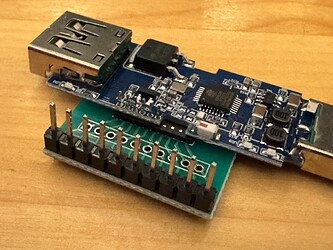
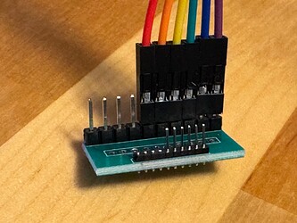
This device allows you to turn the USB device connected to it on and off. It supports data pass through however my main uses are just to turn USB devices, such as a USB Microscope, on and off.
I found some very basic YAML online so I figured I’d create my own. Sharing in case others would like to use it. I split the YAML into two so that you don’t need to edit many files if you make changes to the core functionality in the template file.
While you can use the restore_mode to define the USB port state at boot up, I wanted to be able to configure it so I set it to ALWAYS_OFF and then switch it on if the configured default is On. If it isn’t, then it will switch it off at boot… this is not necessary unless you change the restore_mode to something that may default it to on.
The Red led is wired to the output mosfet that controls power to the USB port so it can’t be configured and will always turn on when the port is on. The green and blue leds are configurable however I let the blue led remain the status_led as I had no other function for it. The green led turns on when the port is off to indicate there is power, and off when the port is on and thus the red led is on. You can now also configure it to be on when the port is on (along with the red), or just disable it to minimize light output & power draw.
If you want to merge all the YAML into one file, remember to remove the extra indent on the YAML in the template file.
I am not a programmer so I am quite sure there are better ways to accomplish what I did… glad to get feedback on how to improve the YAML.
EDIT: For those who will likely tell me that I could have avoided lambda… I used it as it is more compact and IMO versatile. Boils down to personal preference.
microscope.yaml
substitutions:
  devicename: microscope
  devicename_no_dashes: microscope
  friendly_devicename: "Microscope"
  device_description: "Microscope"
  update_interval_wifi: "120s"
  restore_mode_setting: ALWAYS_OFF
  #restore_mode: Control how the relay attempts to restore state on bootup.
  #RESTORE_DEFAULT_OFF          - Attempt to restore state and default to OFF if not possible to restore.
  #RESTORE_DEFAULT_ON           - Attempt to restore state and default to ON.
  #RESTORE_INVERTED_DEFAULT_OFF - Attempt to restore state inverted from the previous state and default to OFF.
  #RESTORE_INVERTED_DEFAULT_ON  - Attempt to restore state inverted from the previous state and default to ON.
  #ALWAYS_OFF                   - Always initialize the pin as OFF on bootup.
  #ALWAYS_ON                    - Always initialize the pin as ON on bootup.

esphome:
  name: "${devicename}"
  friendly_name: "${friendly_devicename}"
  comment: "${device_description}"
  on_boot:
    then:
      - script.execute: on_boot_default_state

esp8266:
  board: esp01_1m
  framework:
    version: recommended
  restore_from_flash: true

wifi:
  ssid: !secret iot_wifi_ssid
  password: !secret iot_wifi_password

  # Enable fallback hotspot (captive portal) in case wifi connection fails
  ap:
    ssid: "${devicename}"
    password: !secret iot_wifi_password
    ap_timeout: 3min

#Faster than DHCP. Also use if can't reach because of name change
  manual_ip:
    static_ip: 10.1.3.218
    gateway: 10.1.2.1
    subnet: 255.255.254.0
    dns1: 10.1.0.50
    dns2: 10.1.0.51

#Manually override what address to use to connect to the ESP.
#Defaults to auto-generated value. Example, if you have changed your
#static IP and want to flash OTA to the previously configured IP address.
  use_address: 10.1.3.218


<<: !include template-usb-port-switch.yaml
usb-port-switch-template.yaml
  logger:
    logs:
      sensor: INFO # DEBUG level with uart_target_output = overload!
      binary_sensor: INFO
      text_sensor: INFO

  # Enable Home Assistant API
  api:

  ota:
    - platform: esphome
      password: !secret ota_password

  web_server:
    port: 80
    version: 2
    include_internal: true
    ota: false

  captive_portal:

  # Sync time with Home Assistant
  time:
    - platform: homeassistant
      id: ha_time

  text_sensor:
    - platform: wifi_info
      ip_address:
        name: "IP"
        icon: "mdi:ip-outline"
        update_interval: ${update_interval_wifi}
      dns_address:
        name: "DNS"
        icon: "mdi:dns-outline"
        update_interval: ${update_interval_wifi}
      ssid:
        name: "SSID"
        icon: "mdi:wifi-settings"
        update_interval: ${update_interval_wifi}
      bssid:
        name: "BSSID"
        icon: "mdi:wifi-settings"
        update_interval: ${update_interval_wifi}
      mac_address:
        name: "MAC"
        icon: "mdi:network-outline"
      scan_results:
        name: "Wifi Scan"
        icon: "mdi:wifi-refresh"
        disabled_by_default: true

  #Alternative, if blue led is needed for something else:
  #https://esphome.io/components/light/status_led.html
  status_led:
    pin:
      number: 16 # Blue LED

  switch:
    - platform: gpio
      id: port_power
      restore_mode: ${restore_mode_setting}
      pin: 5

    - platform: gpio
      pin: 14
      id: green_led
      inverted: false

    - platform: template
      id: usb_port
      name: ""
      lambda: |-
        if (id(port_power).state) {
          return true;
        } else {
          return false;
        }
      turn_on_action:
        - lambda: |-
            id(port_power).turn_on();
      turn_off_action:
        - lambda: |-
            id(port_power).turn_off();
      on_turn_on:
        - lambda: |-
            if (id(green_led_mode).state != "Never" && id(green_led_mode).state != "Always") {
              if (id(green_led_mode).state == "Port On") {
                id(green_led).turn_on();
                }
                else {
                  id(green_led).turn_off();
                }
            }
      on_turn_off:
        - lambda: |-
            if (id(green_led_mode).state != "Never" && id(green_led_mode).state != "Always") {
              if (id(green_led_mode).state == "Port On") {
                id(green_led).turn_off();
                }
                else {
                  id(green_led).turn_on();
                }
            }

  binary_sensor:
    #Status Binary Sensor exposes the node state (if it’s connected to via MQTT/native API) for Home Assistant.
    - platform: status
      name: "Connection Status"
      id: connection_status
      entity_category: diagnostic

    # Button
    - platform: gpio
      id: btn
      name: "Button"
      pin:
        number: 4
        inverted: true
        mode:
          input: true
          pullup: true
      on_press:
        - switch.toggle: port_power

  sensor:
    - platform: wifi_signal
      name: "WiFi Signal"
      update_interval: ${update_interval_wifi}
      device_class: signal_strength

  button:
    - platform: restart
      name: "Restart"
      entity_category: diagnostic

    - platform: safe_mode
      name: "Safe Mode"
      entity_category: diagnostic

  select:
      # option to control how LEDs are used. Red led is hardwaired to output so it cannot be controlled
    - platform: template
      name: "Green LED ON when"
      icon: mdi:led-on
      id: green_led_mode
      optimistic: true
      options:
        - "Port On"
        - "Port Off"
        - "Always"
        - "Never"
      initial_option: "Port Off"
      restore_value: true
      entity_category: config
      on_value:
        - lambda: |-
            if (id(green_led_mode).state == "Always") {
              id(green_led).turn_on();
            }
            if (id(green_led_mode).state == "Never") {
              id(green_led).turn_off();
            }
            if (id(green_led_mode).state == "Port On" && id(usb_port).state) {
              id(green_led).turn_on();
            }
            if (id(green_led_mode).state == "Port On" && !id(usb_port).state) {
              id(green_led).turn_off();
            }
            if (id(green_led_mode).state == "Port Off" && id(usb_port).state) {
              id(green_led).turn_off();
            }
            if (id(green_led_mode).state == "Port Off" && !id(usb_port).state) {
              id(green_led).turn_on();
            }

      # option to disable button
    - platform: template
      name: "Default Port State"
      id: default_state
      optimistic: true
      options:
        - "On"
        - "Off"
      initial_option: "On"
      restore_value: true
      entity_category: config

  script:
    - id: on_boot_default_state
      then:
        lambda: |-
              if(id(default_state).state == "On") {
                id(port_power).turn_on();
              } else {
                id(port_power).turn_off();
              }
Edit: I added the platform under OTA so it works for ESPHome 2024.6+
Edit 19-DEC-2024: Updated code to make sure it is the latest.


