I have been looking for an idea to make smart two way switches and managed to do it.
For this to work, you need at least one spare neutral in one of the wall sockets.
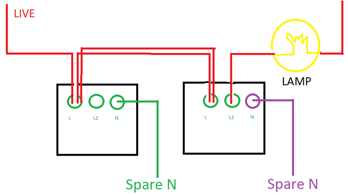
A normal 2 way switch works like this. There are two wires between each socket, one socket has connection to live other has connection to the lamp.
So this is what I did to make to 2 way switch “smart” without any extensive/expensive hardware.
So in the first socket you just power the switch from the live and by pass the mains to the second socket. There are two wires between sockets and if you want you can use both. I end up connecting both to not mess with open end cables. The purple neutral connection is not necessary, but if you have a spare neutral connection in the socket use it. You will get live power usage statistics, plus no “small current” flowing through the lamp even if it is closed.
The first switch is just like a mains powered wireless switch. The automation is as follows:
- id: Auto42
  alias: Toggle Hall Light
  hide_entity: false
  trigger:
    platform: state
    entity_id: switch.wall_switch_ln_158dxxxxxxxxxx
  action:
    service: switch.toggle
    entity_id: switch.wall_switch_158dxxxxxxxxxx
I used xiaomi wall switches for the little project and they cost around 18$'s each (during price drops. which happen quite frequently).
Great idea! I’ve got two of these! Always wondered if there was a way around it!
I’ve now resorted to wiring the WiFi bulbs so they are always on and used Xiaomi wireless switches instead. Don’t like that I wouldn’t be able to switch my lights on if home assistant went down though!
One thing to add. The neutral version aqara switch does not have the wireless mode in mihome app. What wireless mode does is, lt sets the connection of the switch to always on and only reports click events. I tried to do that but the neutral line version does not report clicks and the wireless mode does not stay on.
Maybe in another firmware it will be enabled and my 2 way switch implementation will also have power consumption reporting.
For the purple switch(right one) you can use the no neutral aqara switch. If I remember correctly you will lose power consumption meter if you do so. But for the left one(green switch) neutral switch is necessary.
Thank you for the idea!
I modified this method a bit, I had 3 spare wires to the socket (instead of two) so instead of putting all spare wires into live I:
used the first wire to send L1 to the other switch.
used the second wire to send neutral to the switch without (unnecessary unless there’s no neutral at that switch)
sent live down the final wire
This way, turning on the lights from either switch is instant. They’re in sync via HA or the Mi Home automation. The only lag is on turning off as both switches need to turn off.
I wish there was a way to turn the alternate switch into a wireless switch when the other is activated.
There shouldn’t be any lag whatsoever (if 1/5 or 1/4 of a second is considered instantaneous).
It is only a mater of HA automation and there isn’t, in fact, any need for a physical wire connecting the two switches.You can use any type of switch either in regard of the one that is connected to lights (a neutral or a no neutral version) or the additional switch (a wired or a wireless version):
if there are only two wires at the switch (live and load) you can use the no neutral version (L & L1);
if there are three wires at the switch (live, load and neutral) you can use either the no neutral (L & L1) or the neutral version (L, L1 & N);
wireless switches (or the unused load switch from a multiple loads switch - see below) are then set to toggle the physical switch regardless of its state;
There are also multiple load options for the wired version (L, L1 & L2 or L, L1, L2 & N) of which only one load needs to be connected and the other switch remains “wireless” (ie. not connected to any physical light). This could be used (in HA) to either toggle the other wired switch or for another, completely different function.
One thing that needs to be mentioned is that a single gang wired switch (L & L1 or L, L1 & N) is not really suitable to be used a wireless switch as the device to which load wire goes to will toggle each time the switch is pressed.
I don’t understand the logic behind two Live wires going from switch 1 to switch 2. Isn’t it enough with one wire? Also why would you end up with open end wire when you can totally remove it and use just one wire?
I’m here because I have been looking for something similar. I have a zigbeee network but I use one Nexa switch in the kitchen to be able to dim the lights wirelessly. I want a Zigbee dimmer to work together with the Nexa dimmer. It is just to be able to add this part of the home to my Zigbee network. It seems impossible!
It is about how my cables are connected between my home’s socket. I didn’t want to have lose end cable between sockets and connected both. One is enough of course.
As I’m a noob in electrical wiring, I have a question regarding this, why the first switch (green) required neutral switch? why can’t it use no neutral switch? (I’m assuming there is no neutral wire in both of the socket because the first image didn’t show any neutral wire)
Well those switches are powered through the mains. If you don’t connect to the green wire to neutral it won’t be powered. For the second one the electricity goes through L to L1 so it is always powered even if it didn’t have N connection.
Well, that means it’s not suitable for my case as I don’t have spare N on both switches slot. If I use the capacitor like this to basically create a loop (one end connect to L1 and the other one connect back to L) would that work? Or Did you have a workaround for this?