Smart Switch no neutral wire - fake load, load emulation, bypass capacitor, resistor? etc

I have a pretty interesting setup in the kitchen.

Two work zones, 1 and 2, each have their own line.
I want to use two of the 3-gang touch switches (no neutral) to virtually control different devices in my kitchen.

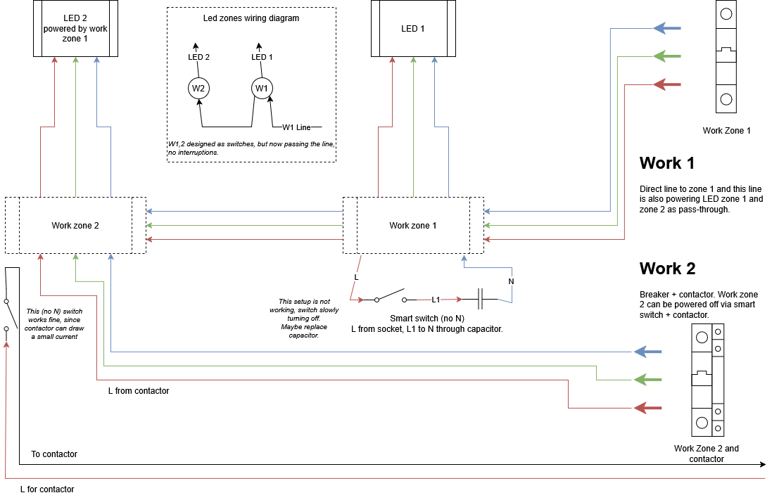
W1 line is a direct one and consists of:

  • a few sockets
  • a branch to LED 1
  • a branch from W1 to the LED2 at W2.

W2 line has a contractor that can power off sockets in that group, and consists of:

  • contactor line to turn it on\off
  • a set of sockets behind the contactor
  • passthrough wires from W1 LED1 to W2 LED2

About the LED:
Initially, it was designed to be a dumb switch, to turn on and off each LED zone from the related W1 or W2 zones. A few years later, I realised that it’s better not to power off LED lines completely if I want to use a smart LED controller. So now all led lines are in full pass-through mode, no breakers. Each LED will have a smart controller now.

The scheme:

The switch:

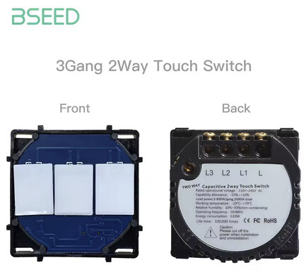
The switch is Zb no-neutral 3 gang.

W2 zone is fine

At the W2, I added this switch for a contactor, and it works fine. There are 2 more buttons which are not connected to anything, that I can use as ā€œvirtualā€ switches, for example, for each of the LED zones (smart LED controller) or anything else.

W1 Zone is problematic

At the W1 zone, I’ve tried to use the same switch, but since there is no load at all, I cannot ā€œemulateā€ a little current draw, so I tried to use a capacitor from another Zb relay

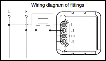
  • This picture is modified to look like the scheme I was trying to achieve with the 3-gang Zb switch.

In short, this switch is completely virtual; there is nothing it can power off. However, there is an LED1 to LED2 line, but I cannot make it breakable, as I want the LED line to be powered on all the time, so the LED controller would not go offline.

What should I do to make this switch work?

Capacitor workaround

  • Change the capacitor to another one that can draw enough current to power up the switch?
  • Add a tiny 220 bulb into the socket box with a capacitor.

Assuming my current test setup capacitor is not enough

Wiring workaround

  • Connect the switch in PARALLEL with the LED.

*So that the LED transformer and controller will draw a little current always, but being in parallel, this switch will not break the circuit.
L from LED line into the switch L AND into switch L1 *

Nothing from above

The last approach with the least brain injury chance would be to buy a switch with N wires, and just connect it to the W1 line L to L N to N. This switch will be only at L\N lines without anything else connected, fully virtual.

N.B. I have a similar setup in the bedroom too, but as soon as I understand the problem at the kitchen setup, I can reuse this experience there.

Thanks in advance.
I will experiment with all my bullets and will update this topic accordingly.

UPD: Similar switch from the same company but WITH neutral wire is working fine, which is the best option for now. Moreover, the N switch is working as a Zb router!

Like you have noticed the cap alone does nothing. You need bulb as well.

Anyway, your way of drawing circuits is impossible for me to understand.
You should draw the ā€œW1ā€ circuit with all actual components and wirings connected to actual contacts labeled.

Ps. First time in my life I see someone trying to use no-neutral smart switch with neutral. Usually it 's opposite… :wink:

1 Like

I tried to answer in your earlier thread, does this help?

1 Like

I bought a few of them, and later I realised not all of them will have an actual load. While waiting for another switch I ordered, now with neutral, I want to give it another chance with no neutral, if possible.

I also ordered a set of caps ā€œAnti-Flicker X2 4.7μF Film Capacitor for No-Neutral Switchesā€ for experiment.

Can’t find a 10K resistor with a suitable size and construction so it can be hidden in the socket box now.

UPD: For the simplest solution, I suppose it’s always better to use a switch with neutral, even if it’s not connected to any actual load, it still should work as a virtual switch, Zb repeater and will not require batteries.

10k resistor at 230V produces 5W of heat, so you have to take care of the heat dissipation.

2 Likes

Yeah, this is another problem to solve.

The space in the socket box in the wall is pretty small, so it can overheat pretty fast, assuming it stays in power on mode forever.

Is that one of those zigbee switch that works only with neutral wire?

These work fine on my BSeed no neutral switches :wink:
5PCS AD K X2 Safety capacitance Tape line 0.22uF 250V-275V

I’m using 3 of them as headless switches.
It was until later i found out they also sell switches for 2-way (hotel) usage (with a separate 2-way switch wire) which are the ones i should have used :thinking:

1 Like

Yep, literally the same, but it has an N wire in the terminal, where the no-N version has a ā€œ2-wayā€ connection.

I have this 2 way ones, and I’m not yet fully comprehend their 2-wayness, it scares me.

My bedroom also have an option to use 3-way switch setup (one light 3 switches to control), but this is even scarier.

One of the switch boxes have 6 wires! OMG. I’m postponing the final setup for those switches more and more, until I feel ready.

I have them as all ā€˜separate’ entities in home assistant.

In other words, my 2 switches itself don’t basically do anything, except talking to HA.
The N-wire goes to neutral, the L(amp)-wire goes through the capacitor straight to 220 (which is only required to power the switch).
So it doesn’t actually switch the light; I can’t do that anyway, as the lamp I use is a zigbee lamp (which also requires to be powered continuously).
In the end it is the home-assistant automation that ā€˜glues’ them all together.

(so yeah, there is a risk; if HA is down, the light wont work…)

1 Like

You did mention that 1 one of the switch needs to be always on as detached. Might consider flashing custom firmware on it to enable that

I’d recommend installing relay behind the last switch wired directly to the light like zbmini L2.
Easiest way is installing sonoff basic r4 on the light fixture with minimal wiring job. But it’s wifi though not zigbee

2 Likes

You may also consider reducing the number of relays you are using by essentially turning some of the wall switches into toggle sensors with something like the Sonoff S-Mate. That was the best solution to smartify a couple of the 3-way switched circuits in our home.

The fact that they require a battery change every couple years is less of a con, for me, than worrying about possibly dodgy bypass capacitors or resistors.

1 Like

Oh I have a few of them, thanks! It’s a pretty nice hack.

The Bseed switch isn’t supported (yet), only the 2 gang.

But as soon as I have my spare one back, I’ll have a go at it :innocent: