Smart switch wiring to multiple switches

My goal: Control the living room light from multiple locations.

Hardware I have:
Three 2-gang 2-way toggle switches (in bedrooms)
Terminals: LA, LA1, LA2, LB, LB1, LB2

One 1-gang 2-way toggle switch (in living room)
Terminals: L, L1, L2

Several noname WIFI smart switches from China
Input and output: AC 100–265V
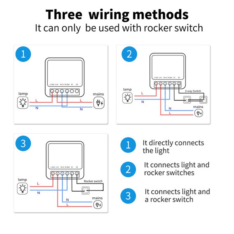
Terminals: L-out, L-in, N-in, N-out, S1, S2

What I did:

Light: L wire to smart switch L-out, N wire to N-out
AC: L wire to smart switch L-in, N wire to N-in
All the wall switches are connected in parallel as following:
1-gang switch: L is connected in parallel to smart switch L-in, L1 is connected in parallel to smart switch S1

2-gang switches: all LA are connected in parallel to smart switch L-in, all LA1 are connected in parallel to smart switch S1

For test benching I wired up all the wall switches, the light bulb, and the smart switch using block terminals, and powered everything through a plug cord.
During testing, I hadn’t checked the polarity in the wall socket beforehand, so it’s possible I plugged the cord in reversed, also I accidentally connected all the L1 and LA1 wires to the N-in terminal. This caused a brief one-second blackout, but I immediately unplugged the unit—there was no visible damage or burning smell. After ‘correcting’ the wiring and connecting it properly(? Still haven’t checked the polaruty in the wall socket) to S1, I turned on the AC. The smart switch immediately blew out, though this time it didn’t trigger a blackout.

I tested each switch individually and they all appear to be functioning correctly. I also noticed that all four switches were in the ON position.

Here’s my question:
Is my wiring diagram even correct, or am I doing something fundamentally wrong or maybe even attempting the impossible? Should I give it another shot with a smart switch that’s the same model I have lying around?

Ps: Unfortunately I can’t upload more than one picture per post

Here the instructions wiring

The second line above the wiring diagram states “It can only be used with rocker switch” in fairly large font. So what made you think it was safe to connect S1/S2 to another smart switch? None of the wiring diagrams connect either one to live. Most likely the S1/S2 are not built for 100-265V and this fried the internals.

In all honesty: if you need to ask this question, you should let the wiring be done by professionals.

If your intent was to have multiple rockers for a smart light that is controllable by HA then one smart switch would have done the job, as per wiring scheme 2 on the top right. It does not make sense to have two ways for HA to control the same light.

I’m new to HA and electrical work—just starting out on my learning path. Also english is not my first language and some mistakes in my are very likely posts are very likely to happen, but I think I clearly wrote that I connected all 4 wall switches to only 1 smart switch and my goal is to control the living room light from multiple locations(4 rooms and over HA).
I started this topic hoping that more experienced users or someone who’s already worked with this specific smart switch might have tried something similar before and could share their input.
I guess on/off rocker and toggle switches are basically the same and from what I understood, wiring diagram 2 allows only two 2-way switches.

No one here can see or check what your home wiring is. The best you will get is guesses, and you have no idea if the person ‘helping’ has any idea or not.
Keep in mind if you know what you are doing, I have no problem helping. But when you clearly do not know anything about the wiring you are looking at then PLEASE get help from someone that does.

Disclaimer

:warning: DANGER OF ELECTROCUTION :warning:

If your device connects to mains electricity (AC power) there is danger of electrocution if not installed properly. If you don’t know how to install it, please call an electrician.

Beware: certain countries prohibit installation without a licensed electrician present

Remember: SAFETY FIRST. It is not worth the risk to yourself, your family and your home if you don’t know exactly what you are doing. Never tinker or try to flash a device using the serial programming interface while it is connected to MAINS ELECTRICITY (AC power).

Wow… I’m not trying to sound rude, I’m still working on expressing myself more clearly, so I understand that sometimes my messages might be a bit confusing, but either my english is worse than I thought, or reading an entire post before replying is suddenly out of fashion. My bad for expecting too much.

That said, I genuinely welcome constructive criticism pointing out my mistakes, suggesting better approaches, or even tossing in assumptions or hints that could lead somewhere useful. The previous reply from Edwin_D wasn’t perfect, but it did push me to consider a few things I hadn’t thought of, so I appreciate that!

Generic responses, though? They don’t really help move the conversation forward and feel more like filler posted just for the sake of profile stats. Just saying. No offense.

I’ll update the main post with more pictures as soon as my user status allows. Hopefully it’ll make things clearer for both the community and future internet diggers who end up here chasing down the same issue.

Replace the circled part

with this

and you can add as many cross-switches (middle part) as you wish

1 Like