Hello, I have a programming background so I have hard time figuring out hardware pieces of the RF bridge.
My pool lights have a bad RF receivers so I need to put RF Bridge very close to them to be able to turn the lights on/off (even original rf remote works only when being close or antenna extended to the full).
My idea is to solder external antenna to the RF bridge board, something similar like this guy did: Sonoff wifi Antenna extender IOT - YouTube.
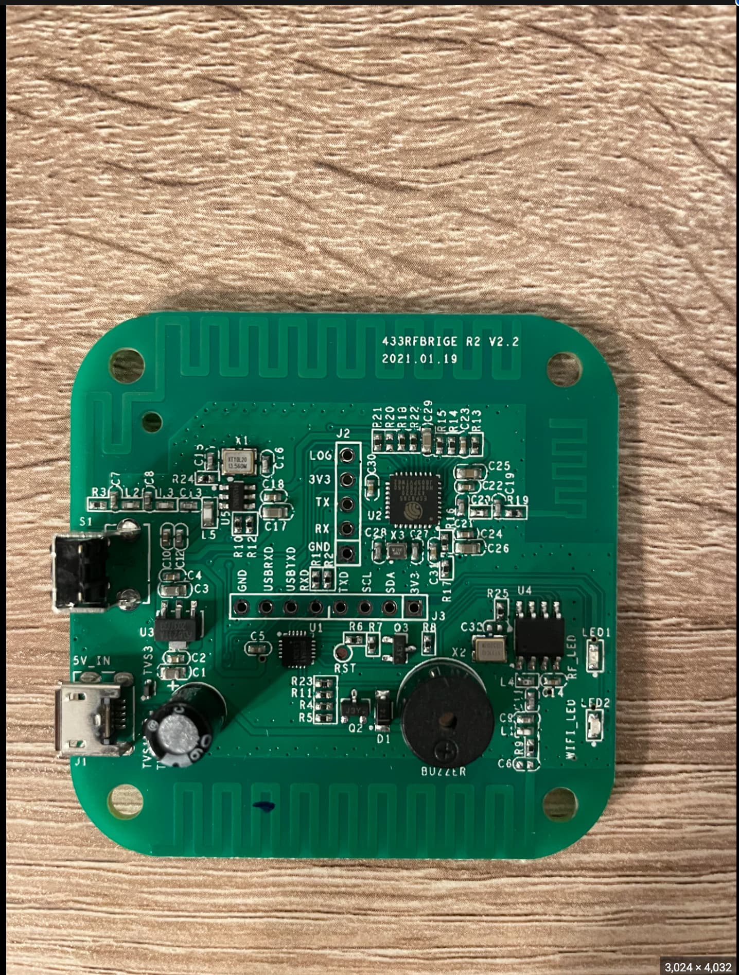
Can anybody help me identify the transmitter antenna on the R2 v2.2 PCB so I can solder the external antenna on it? There are 3 antennas and I don’t know which one is the transmitter one.
I saw an older version id the Tx and Rx. I assume they haven’t changed that much on the newest version. I haven’t replace the antenna on my RF bridge but I have on a SRX882 receiver by soldering on an uFL IPx to SMA connector. I had to cut the IPx connector off and solder inner core to the trace leading to the antenna and outer core to ground of the PCB. This could be a good chance to build your own ground plane antenna or simple dipole for 433mhz. I found both to work very well for receiving. Better than the built in antenna of the RF bridge. Any chance you could alter the antenna on the lights unit. Antennas are a whole new rabbit hole to go down.
P.S. antennas bought online can be disappointing. That one looks like a monopole with too much thin coax and no end connector.
Thank you very much for your fast response.
The distance between the location of the bridge and the furthest pool light is no more than 15 meters. Do you think that would be ok with the aliexpress antenna? I also choose that one because it has only one line to solder if I’m not mistaken
Something non-related to the bridge itself, but also when using the pool lights “original” remote control is that turning the lights ON works perfectly even at greater distances, but I must come close to turn them OFF. Is there any explanation for this?
When capturing radio signals, in the package there are “Sync”, “Low” and “Right” values too. Can we increase the strength of the signal by manipulating these values?
I did compare the turn ON and turn OFF data but I didn’t find anything so different besides the “data” property itself.
With direct line of sight it may be ok. The more objects in the way the more likely the signal will get lost. It’s about 15m from my unmodified RF bridge to my mailbox 433 transmitter. There is just glass in the way and sometimes branches from a shrub get in between. Particularly if its raining I may not get a signal. I have another receiver esp8266 with a 16.5cm antenna connected and it works better even through wooden floor and brick wall and shrubs. The aliexpress antenna will have a coax cable. Again the cable looks too long and thin. The shortest cable length you can manage will help. In my setup it’s about 15cm. You probably will still need to solder the outer braided part of the antenna to the ground of your receiver to improve reception. Make sure none of the outer braid is in contact with center core or reception will be terrible. Saying all that sometimes things just work anyway.
In my SRX882 there is ground solder point next to solder point for core where I could solder some of the outer braid to. If there wasn’t then I would have just scrapped some of the solder mask off board to get down to the ground of the board. The board came with a coil antenna that just solders to the antenna hole. I didn’t find it any use.
The crystal I point out at the bottom may be why your lights doesn’t turn off as well when it has been on. It’s possible as the device/crystal heats up as it’s used and the frequency slips a bit from the 433.92mhz and you have to get closer then. If you switch it off and then go back to further away point where you could switch it on first I wonder will it switch on as well or do you have to wait for it to cool down?
Thank you for all the tips. I already ordered that antenna but I will cut the cable as much as possible as your suggestions. I don’t think I will need it more then 15-20 cm.
Actually, the problem with turning OFF pool lights is not correct. For one light both actions work fine but for the other one in 30% cases, the turn ON/OFF actions don’t work. Probably something is wrong in how this second light is installed, or something is covering its receiver. I will try to see if I can do something about it once you empty the pool this summer.
I would suggest to try a side SMA RF connector that can be attached to the board. Side pins need connecting to ground which is all the dark green bits under solder mask so needs scraping to get at copper. and original meandering antenna will have to be cut or it’ll throw off the impedance.
I have connected these on before to esp32 board and it worked very well.
Don’t waste your time with a rubber ducky antenna that’s just 5cm long. It will be worse than the internal antenna. Better to try a 1/2 wavelenght dipole , which will be just over 30cm long or a ground plane or J-pole. You will most likely be changing the Effective Isotropic Radiated Power (EIRP) if you use this on a transmitter which could be breaking regulations depending on your country.
Looking more at the board I think this is more like the modification needed. The outer legs of the sma connector need to connect to ground which is the lighter green but a wire. The dark green is not ground. The section in yellow is the matching for impedence. This may cause problems with attaching external antenna as it’s designed specifically for the IFA that was originally used. Matching your new antenna with it might be difficult.