I’ve been expanding my collection of connected devices and am now playing around with the Sonoff SV.
Thanks to the incredible guidance by this community I’ve been able to connect it to a switch and a sensor on GPIO14 (like in the famous DrZZs garage video)
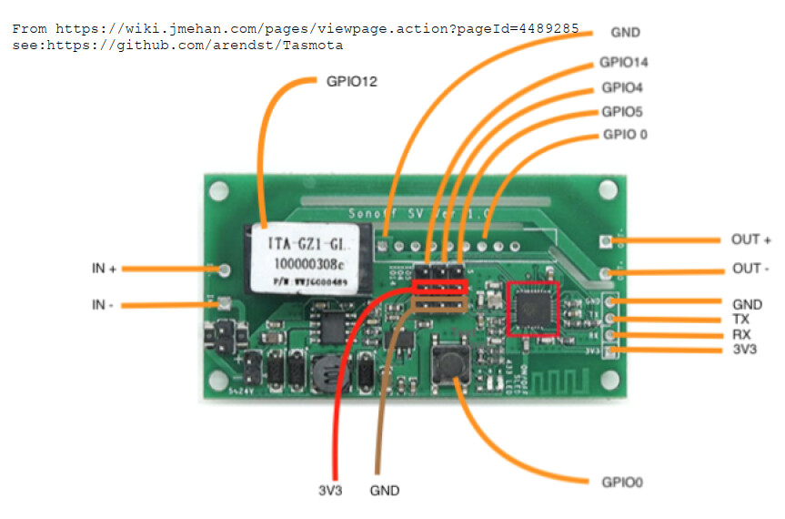
My question is about the rest of those pins. The SV has 9 GPIO pins. I’m assuming 4 of those are the 3.3V, RX, TX, and ground pins. One is GPIO14. What are the other for?
Is there a way to connect more sensors to the rest of the pins? Like is there a GPIO13 and GPIO7 that I could connect more reed switches to?
Tom, looks like you are my champion. Thanks for this too.
That makes a lot of sense. Can you recommend a place where I can read more in how to use GPIO4 & 5 in the same way as 14? I’m not bad at Googling, but couldn’t really find anything. Can I just assign Switch3 and Switch 4 to GPIO4 and 5?
Yes indeed you can. Both those pins have no special caveats. Here’s a handy table that tells you the best pins to use and it looks like Sonoff chose wisely:
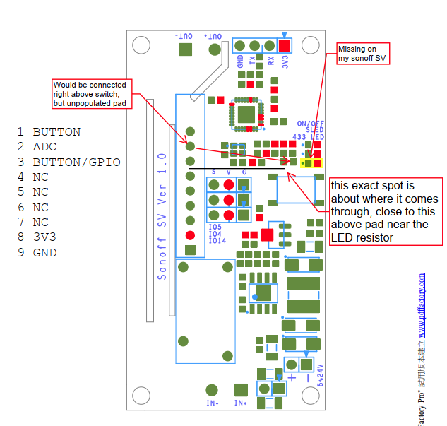
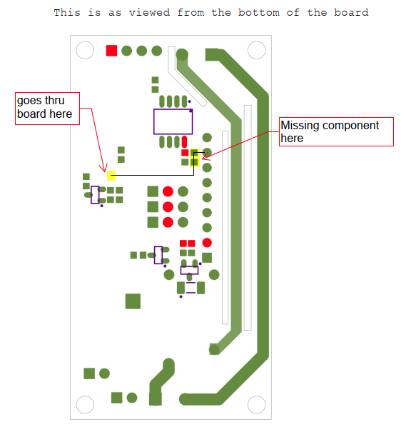
I just want to confirm that we are talking about the same pins. The block of 9 pins (3x3) I get - it’s the other 9 that I’m curious about. Actually, they are not pins but a header (is that the right word?!). I’m curious about the ones I’ve more carefully highlighted here.
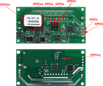
On the attached image, is an additional GPIO which I used to use when I had this operating my gate, as the onboard relay was ideal for this use case, but eventually ran out of flash for everything that I wanted to include onto the board, so I moved over to an ESP32-S2 instead.
I basically used GPIO13 as the “Bell Button” (binary switch) for gate door bell on the kitchen node, and GPIO0 had an external straw hat LED connected to it for the “Gate Bell Button Backlight”, with GPIO14 for the reed switch to detect when the gate was open/closed, GPIO12, obviously the relay and GPIO4&5 (SDA & SCL) used for the INA219 to measure current/voltage/power on the gate battery. Never bothered with TX/RX (GPIO1 & 3) as those would have been a pain when having to flash via USB TTL