Disclaimer: Proceed at your own risk. I’m not responsible for any permanent damage that might occur due to this modification.
Hello,
I encountered the same issue with this device and found a workaround by disabling the relay.
Quick Guide:
- Safety First: Ensure all power to the device is turned off, or better yet, unplug the device.
- Opening the Device: It’s quite straightforward to open it using a plastic card or a guitar pick. Just slide it along the seam between the two halves.
- Locking the relay in the ON state: Locate the first relay pin on the left and sever its connection using a cutter or a sharp blade. I made a deep scratch in the middle of the solder joint, which allows for a possible reversal by resoldering it in the future.
Note: This will effectively disable the relay function, almost permanently. To restore functionality, you’d need to resolder this pin.
In-depth Instructions:
The ZBMini-L2 features a dual coil latching relay, enabling it to maintain its state indefinitely after being set to either allow or block current flow.
Identify the relay on the board by the large black component that clicks. It connects to the main board with 4 pins on the right and 2 larger pins on the left:
- On the left:
- First pin: RESET command. The control board sends an OFF signal here to reset the relay, cutting off current flow.
- Second pin: SET command. The control board sends an ON signal to set the relay, allowing current to pass.
- Third pin: +5V
- Fourth pin (below the third): 0V
- On the right:
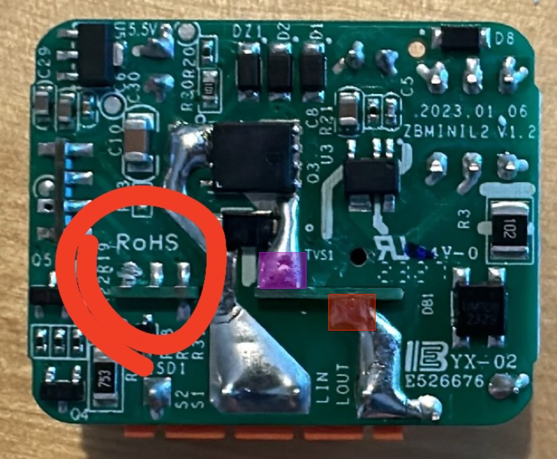
- Larger pin (purple square in the image): AC power input (similar to LIN).
- Larger pin (red square): AC power output (LOUT, leading to the bulb).
With this knowledge, you have several options:
- Bypass the Relay: Shorting the two large pins allows current to always flow to the bulb, but you’ll still hear the relay click.
- Disable the SET Pin: Cutting the SET signal means the relay can never be activated, which is not useful as no power will reach the bulb.
- Disable the RESET Pin: Cutting the RESET signal means the relay can never be deactivated, which suits our purpose.
- Extreme Measures: Consider removing the relay entirely by desoldering all its pins and shorting the two large pins. If you have access to a 3D printer, you could potentially design a smaller case for the device.
Disabling the RESET pin is nearly ideal as it stops the relay from clicking and ensures continuous current to the light. You will also still get the information of the switch position in the device, so you can make automation with it.
Ensure a deep enough cut in the solder joint to avoid accidental contact. Be careful not to damage other components.
Tip: A vertical blade works well. Press it against the soft solder and scratch until you reach the board.
Drawbacks:
- Remote power cut-off isn’t possible; you’ll need to rely on smart bulb features.
- If the bridge fails, the switch won’t control the light directly. In my case, if the bridge is down, I’d have bigger issues to deal with.
