First of all, sorry if any term is not correct. I am starting with the DIY of home automation and electrical issues, although I know something, I am not a professional. Also, I am not native english speaker person.
I have bought several Sonoff ZBmini-L2 (those that go without a Neutral cable). I installed a few in relay mode without smart lights, cutting the current, and they work perfect integrted in HA with ZHA. For the bedroom area I wanted to have the possibility to change the tone of the light so I thought I could make a bridge to the traditional switch installed on the wall to keep the bulb always connected and use the ZBmini-L2 to obtain the status of the traditional switch and, through HA, program an automation to turn the bulbs on and off.
The thing is that when testing it, the ZBMini-L2 does not turn on if it does not have a load on the Lout gate.
I have set it up like this:
S1 and S2 to the traditional switch (you can also just to S2).
In ZBMini’s Lin I put the signal that also feeds the smart bulb, but with this the Sonoff does not turn on.
My idea is to keep the traditional switches (for home aesthetics - the house is new and I don’t want to change all of them).
Also say that the switch box does not have Neutral cables, only Line. I had seen this post: How to combine Sonoff ZBMINI with Zigbee smart bulb where it seems that the previous model does allow the relay to be jumped connecting everything to Lin but it requires a Neutral (I would have to pull a cable) and due to space I am not sure if it fits in the switch box.
Is there a way to power the ZBmini-L2 without using the relay?
If it helps mi tradicional switches are these: N2202 NIESSEN ZENIT
The way the ZBminil2 works (same as all no-neutral relays) is that the “off” state still allows a very small current flow so that the relay stays powered, but the load (usually a lightbulb) is unpowered.
As you discovered, if you do not connect the load, the ZBminil2 remains unpowered, because the circuit is open.
Furthermore, using the ZBminil2 to switch a smart lightbulb won’t work the way you want. This is because you always want to have the smart bulb powered so the network stays up, but there is no way to flip the switch in the ZBminil2 without switching off the load.
Disclaimer: Proceed at your own risk. I’m not responsible for any permanent damage that might occur due to this modification.
Hello,
I encountered the same issue with this device and found a workaround by disabling the relay.
Quick Guide:
Safety First: Ensure all power to the device is turned off, or better yet, unplug the device.
Opening the Device: It’s quite straightforward to open it using a plastic card or a guitar pick. Just slide it along the seam between the two halves.
Locking the relay in the ON state: Locate the first relay pin on the left and sever its connection using a cutter or a sharp blade. I made a deep scratch in the middle of the solder joint, which allows for a possible reversal by resoldering it in the future.
Note: This will effectively disable the relay function, almost permanently. To restore functionality, you’d need to resolder this pin.
The ZBMini-L2 features a dual coil latching relay, enabling it to maintain its state indefinitely after being set to either allow or block current flow.
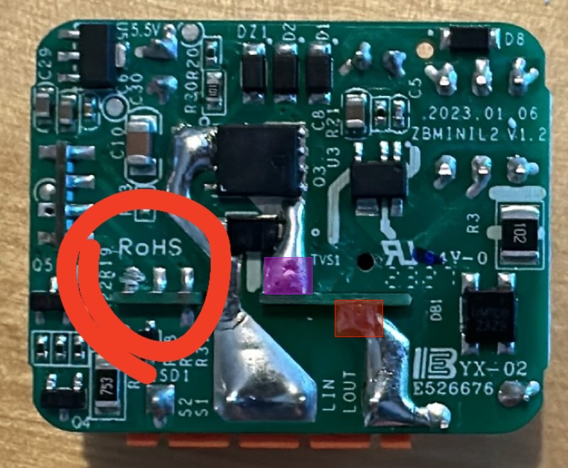
Identify the relay on the board by the large black component that clicks. It connects to the main board with 4 pins on the right and 2 larger pins on the left:
On the left:
First pin: RESET command. The control board sends an OFF signal here to reset the relay, cutting off current flow.
Second pin: SET command. The control board sends an ON signal to set the relay, allowing current to pass.
Third pin: +5V
Fourth pin (below the third): 0V
On the right:
Larger pin (purple square in the image): AC power input (similar to LIN).
Larger pin (red square): AC power output (LOUT, leading to the bulb).
With this knowledge, you have several options:
Bypass the Relay: Shorting the two large pins allows current to always flow to the bulb, but you’ll still hear the relay click.
Disable the SET Pin: Cutting the SET signal means the relay can never be activated, which is not useful as no power will reach the bulb.
Disable the RESET Pin: Cutting the RESET signal means the relay can never be deactivated, which suits our purpose.
Extreme Measures: Consider removing the relay entirely by desoldering all its pins and shorting the two large pins. If you have access to a 3D printer, you could potentially design a smaller case for the device.
Disabling the RESET pin is nearly ideal as it stops the relay from clicking and ensures continuous current to the light. You will also still get the information of the switch position in the device, so you can make automation with it.
Ensure a deep enough cut in the solder joint to avoid accidental contact. Be careful not to damage other components.
Tip: A vertical blade works well. Press it against the soft solder and scratch until you reach the board.
Drawbacks:
Remote power cut-off isn’t possible; you’ll need to rely on smart bulb features.
If the bridge fails, the switch won’t control the light directly. In my case, if the bridge is down, I’d have bigger issues to deal with.
Hi Tronix, I did exactly as you said, and it seems to work. The relay isn’t being triggered when I use the switch and the device is still getting power. The only thing is I cannot seem to re configure the zbminil2 in home assistant now. Before I did the modification I did a factory reset. Now when it enters pairing mode my ZHA integration doesn’t seem to find it and it falls out of pairing mode after like 15 seconds.
Any idea what is going wrong? Perhaps the modification disabled the functionality of pairing the device?
Upon further investigation, the mini loses power after the smart bulb is switched off (turning the bulb itself off through HA suffices).
In short, the mini is not suitable for the purpose of functioning as a smart switch only without output of with a smart bulb as an output, even after hardware modifications. I tried both cutting reset and soldering the relay.
I’ve been trying to find a no neutral switch with “detached relay mode” (or no relay at all) for more than a year…
Just found today the article, and it works like a charm: I’ve converted 3 of my ZBMINIL2 to “detached relay”, and they are now independent from the always-on Philips Hue bulb, the IKEA pendant lamp, and the Zigbee 24VDC dimmer!
I’m super happy because I can at last activate a scene/routine using the pre-existing wall switches from my rental apartment (event triggered by the change of state of the switch), and keep my devices (load) always powered/connected.
It was a bit of a challenge to open and cut the 1st one as the working area is only a couple of mm wide, but then it was super easy for the next ones.
@schapendonk.brent, and @Telnoi: I had similar problems for one of my ZBMINIL2 that became completely unresponsive (neither using the switch, nor via SmartThings). After having disconnected/reconnected it several times from the wall circuit, it worked again. None of the ZBMINIL2 were factory reset, they continued to work with my controller.
Now, I can’t recall if I plugged the ZBMINIL2 always the same way, but have you checked if:
the L-in connected to the line
and the L-out connected to the load?
Not sure if it can be an issue or not, but as this is a no-neutral setup, it might have an impact.
I have a somewhat different use case in mind, but struggle to understand if this will work with the ZBMINIL2. Hopefully you can shed some light on this.
I have smart lights on presence sensors everywhere, the (now still) dumb light switches are merely for back-up and the occasional power cycle.
Everything works like a charm, but I want to make the system resilient against accidental light switching off (e.g. a guest switching off the light after toilet use).
Can I use the ZBMINIL2 (no neutral) to “merely” switch the power back on, say 10 seconds after somebody switches it off?
@Tronix117 , I wish I could buy coffee
I came to find out about this just the other day, I tested with L in L-in and N in L out without any resistance Boooyy did I find out.
Thankfully circuit breaker intefered.
After the short the ZBMINI-L2 surprisingly still worden and the relay did “click” but the NC/NO switching did not work. In essence I detached the relay I believe.
However, you method is much safer and you can always revert back.
@Tronix117 Thanks for the tip. I’ve followed your instructions and it’s working as described. However, there’s still one question.
You will also still get the information of the switch position in the device, so you can make automation with it.
I created an automated for toggling the light when ZBMini-L2 state changes. This is working fine, too. However, this is a bit unusual way of configuring a light switch. Normally, I’m binding my switches to the lights so that they don’t rely on the controller to be running. I’ve noticed that Zigbee2MQTT does not allow me to create a binding for the ZBMini-L2. Is there a way around that?
I followed your solution cutting the first connection. It did work for the first when turning the power back on. However, after turning the power off a couple times to modify the other ones, all of them don’t get recognized anymore. I configured all of them first using ZHA, but none of them are controllable anymore. Also, the reset button doesn’t do anything, no light anymore. It seems like they are bricked. Did someone else have this problem after applying the modifaction, and a possible solution?
It’s a bit dirty, but you could install the ZBMINI as a traditional relay (like with your dumb lights) and then make an automation that triggers upon the switch turning off and immediately turn the switch back on and thereafter toggle your smart light
Thank you for this. I’m looking to achieve the opposite with the existing light - I want it to always be off. I have a conventional light with live in and out (no neutral), and I’d like to add a second switch which I only want to use for Home Assistant to receive the toggle event from a ZBMINIL2. I essentially want to use the wiring from the exsiting light as a power source for the ZBMINIL2, but I don’t want it to turn on the existing light. Is that possible?
Edit: To anyone looking for the same solution, I cut the SET pin and left the RESET pin attached. This allowed me to wire the ZBMINIL2 across the existing, non-smart light switch, just to use its power. The physical switch wired to the ZBMINIL2 then worked purely to send events to HA, and the non-smart light worked as normal.