Hi @all,
Important
I am no good electronics guy, nor should this bring anyone who is not able/approved/sure to tamper at his door phone system. Take care of everything you do, and in case of doubt ask a parent.
Proloque
As someone with a toddler, turning off the doorbell is a pretty common thing. But, if you order a ton of stuff online you will find yourself shouting at the Amazon delivery guy who bangs at the door and screams for you, to get his package delivered. Thanks for waking up my little boy. Really good job…
As I am not very deep into electronics, I just scraped all information found and tried to get it done on my system, as I did not find some clear “Hey, you have some HTA 811, this is how I did it”. So here it is.
As I was not interested in opening the door remotely I did not add any relay or similar for this. My target was to get some sensor at HA to e.g. send notification or flash some lights.
Needed Parts:
- WeMos D1 Mini
- 2 rectifier (Brückengleichrichter) DB107
- 1 optocoupler PC817C
- 1 1K resistor.
HTA vs. HTS
A pretty common system here in Germany is made by SSS Siedle. I have some HTA 811. The A is some important information, as it tells it is the analog version. There is also HTS out there, which has way more features and some other power supply.
In short:
- HTA: AC Powered
- HTS: DC Powered
HTA 811
Adding electronics
Power Supply
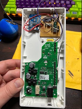
I was able to hijack the door opener button. It has constant ~12V (iirc) AC available. Using some rectifier and a 5V BEC i was able to power the ESP8266. In my case some little capacitor was needed to make sure the BEC worked. I guess some AC-DC bucket converter would do the job too. But this was laying around.
Recognise the bell
The moment the bell was pressed on some line there was the same ~12V available. By using a recitifier and some optocoupler i was able to just use one GPIO. It needed some 1k resistor to work.
Photos
First breadboard prototype
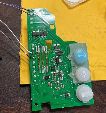
I simply soldered to the board of the phone itself. This is the only impact on the existing system and can be replaced by using the screws of the yellow block.
I threw all stuff against some perfboard. It is not pretty, but it works.
Software
I just used ESPHome for this job.
esphome:
  name: tuerklingel

esp8266:
  board: d1_mini

# Enable logging
logger:

# Enable Home Assistant API
api:

ota:
  password: "XXX"

wifi:
  ssid: !secret wifi_ssid
  password: !secret wifi_password

  # Enable fallback hotspot (captive portal) in case wifi connection fails
  ap:
    ssid: "Tuerklingel Fallback Hotspot"
    password: "XXX"

captive_portal:


binary_sensor:
  - platform: gpio
    pin:
      number: D2
      mode:
        input: true
        pullup: true
      inverted: true
    name: Klingel
    filters:
      - delayed_off: 50ms
That’s all needed to do.
As said, I am no good electronics guy, so I did not post links to what I bought on purpose.
Sure, using some optocoupler with integrated AC/DC would be possible, but was not available for me quickly.
Hope this will help someone. Make sure to read the links below, they might explain it even better.
Greetings
Max
Good to read:


