Dizzwold
December 15, 2024, 4:54pm
1
Hi Guys,
I’m trying to implement a stepper motor in esphome but something must have changed recently regarding inverting a pin.mapping values are not allowed here in "/config/esphome/curtain-steppertest-1.yaml", line 61, column 14 inverted: True
I can’t understand why this isn’t accepted. Heres the full sketch;
esphome:
  name: curtain-stepper-test-1
  friendly_name: Curtain Stepper Test 1

esp32:
  board: esp32dev
  framework:
    type: arduino

# Enable logging
logger:

# Enable Home Assistant API
api:
  encryption:
    key: "xxxxxx"

  #services:
   # - service: shaft_target

ota:
  - platform: esphome
    password: "xxxxxx"

wifi:
  ssid: !secret wifi_ssid
  password: !secret wifi_password

  # Enable fallback hotspot (captive portal) in case wifi connection fails
  ap:
    ssid: "Curtain-Stepper-test-1"
    password: "xxxxxx"

    services:
      - service: position
        variables:
          target: int
        then:
          - stepper.set_target:
            id: st1
            target: !lambda "return target"
captive_portal:

number:
  - platform: template
    name: Stepper Control
    optimistic: True
    min_value: 0
    max_value: 2000
    step: 1
    on_value:
      then:
        - stepper.set_target:
            id: st1
            target: !lambda 'return x;'

stepper:
  - platform: a4988
    id: st1
    dir_pin: 17
     inverted: True
    step_pin: 21

    max_speed: 1000 steps/s

    sleep_pin: 22
     inverted: True
    acceleration: 800
    deceleration: 800
WallyR
December 15, 2024, 9:08pm
2
I had a similar experience with a serial setup.
Rudd-O
December 15, 2024, 10:43pm
3
That is highly illegal YAML. Look at the docs again for proper form.
Dizzwold
December 16, 2024, 2:50pm
4
Hi Guys,
Thank you for your replies. Im very grateful.
I’ve edited the sketch, and it will now compile and upload, but I get nothing from the motor if I move the slider.
  name: curtain-stepper-test-1
  friendly_name: Curtain Stepper Test 1

esp32:
  board: esp32dev
  framework:
    type: arduino

# Enable logging
logger:

# Enable Home Assistant API
api:
  encryption:
    key: "xxxxx"

ota:
  - platform: esphome
    password: "xxxxx"

wifi:
  ssid: !secret wifi_ssid
  password: !secret wifi_password

  # Enable fallback hotspot (captive portal) in case wifi connection fails
  ap:
    ssid: "Curtain-Stepper-test-1"
    password: "xxxxx"


captive_portal:

number:
  - platform: template
    name: Stepper Control
    optimistic: True
    mode: SLIDER
    min_value: 0
    max_value: 100
    step: 1
    on_value:
      then:
        - stepper.set_target:
            id: st1
            target: !lambda 'return x;'

stepper:
  - platform: a4988
    id: st1
    dir_pin:
      number: GPIO17
      inverted: True
    step_pin: GPIO21

    max_speed: 250 steps/s

    sleep_pin:
      number: GPIO22
      inverted: True
    acceleration: 800
    deceleration: 800
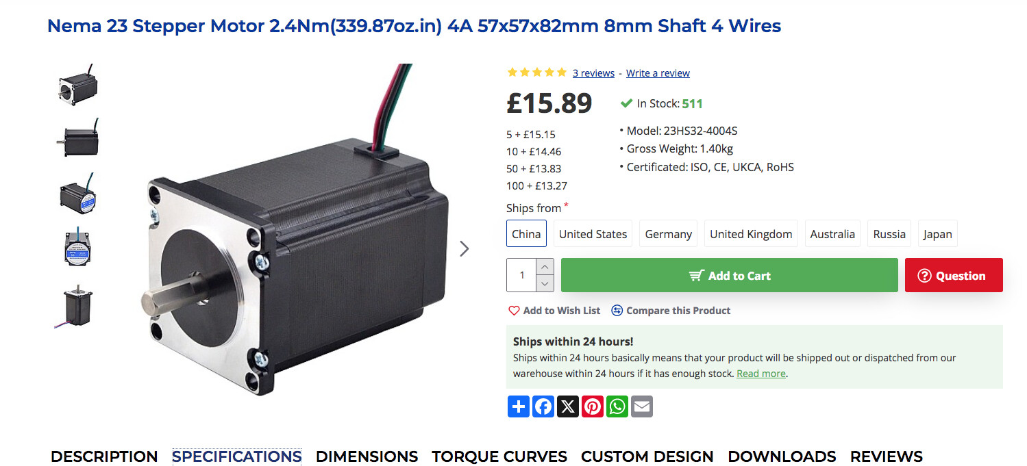
This is the driver I have and the Nema 23 motor.
https://www.aliexpress.com/item/1005004822801078.html?spm=a2g0o.order_list.order_list_main.35.b9b61802Uy8FXE
https://www.omc-stepperonline.com/nema-23-stepper-motor-2-4nm-339-79oz-in-4a-57x57x82mm-8mm-shaft-4-wires-23hs32-4004s
I have a 24v 600w PSU connected to the driver COM and VM (- & +).
Should my sketch theoretically work, or is it my wiring?
3ATIVE
December 16, 2024, 4:18pm
5
Check the datasheet for that interface board… you may not need to invert the “Sleep Pin”
Karosm
December 16, 2024, 4:23pm
6
You also need to connect all three - to GND
3ATIVE
December 16, 2024, 4:38pm
7
… A quick Google-ing later:
Dizzwold
December 17, 2024, 7:36am
8
@3ATIVE @Karosm @Rudd-O @WallyR
Thank you guys for your replies. I’m most grateful.
I’m waiting for the retailer to reply with the data sheet.
So Dir -(negative), Stp- (negative), and En - (negative), all need connecting to ESP32 - Gnd.
1 Like
Dizzwold
December 17, 2024, 7:38am
9
@3ATIVE just spotted your googled reply, Ill give that a go.
Dizzwold
December 17, 2024, 7:49am
10
@3ATIVE before you loose the google info, where exactly did you find that information?
I’ve found very little information on this driver board, I’ve even got the seller trying to tell that it can use Stallguard which I think is a load of dogs gonads to be honest.
Karosm
December 17, 2024, 10:39am
11
Which should be common ground with driver board.
Dizzwold
December 17, 2024, 11:24am
12
@Karosm @3ATIVE
Solved By @Karosm & @3ATIVE in the posts above.
Thank You Guys.
I’m now up and running, or should I say rotating.
You were both correct with your replies.
I needed En to be High and not Low, and i needed a Gnd from the ESP to Dri-, Stp- and En- (- Negative).
I can now tinker away and start experimenting.
Thank you again.
Dizzwold.