Hi all,
as I’ve recently moved and now live in a flat with “Rolladen”, I’d like to automate them and checked out the Superrollo GW60. As readers might know, they’re electronic but “dumb” and need extra hardware to integrate.
Now, (a) I find the idea of purchasing the ZB60 remote frankly ridiculous, and (b) the GW60 doesn’t actually work properly for me because my “Rolladen” are quite old and have dead points where they don’t continue rolling down unless you wiggle the straps a bit. This means rolling up works perfectly fine but they don’t come down properly. Whether this can be fixed by driving the motor in some other manner (e.g. back- and forth) I don’t know, but the original GW60 simply cannot do this. Either way I decided to take one apart and reverse engineer the schematic.
Since, well, like probably most of us, I have a ton of random projects, there’s a good chance I won’t continue doing anything on this for a while, so I decided to post the schematic here.
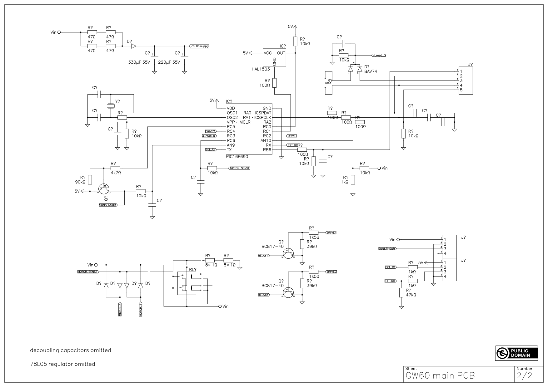
A few notes:
- there’s a 78L05 power regulator I was too lazy to include
- I left out all decoupling capacitors
- the relay is a Omron G8ND-2 DC12. Funnily enough, it’s end of life, they’ll have to pick another one. I didn’t fully reverse engineer the circuitry around it since it’s kinda obvious.
- also 2 freewheeling diodes on the relay coil drives aren’t included
- it uses a PIC16F690 microcontroller, which at this point is politely described as “antiquated”.
- there’s an 8-pin “pad land” that presumably plugs into the ZB60 module. I don’t have the ZB60 module, so I don’t know what that looks like. It has 2 pins from the microcontroller going to it, and those pins can carry UART RX and TX, and it is quite likely that they do. If I had the ZB60 I’d probably solder on some wires and capture traces, but I don’t, so I can’t.
- it uses one reed switch and one hall sensor to determine whether the strap and roll are moving, respectively. Those have to be in exact positions to line up with magnets in the small roller and large wheel, respectively.
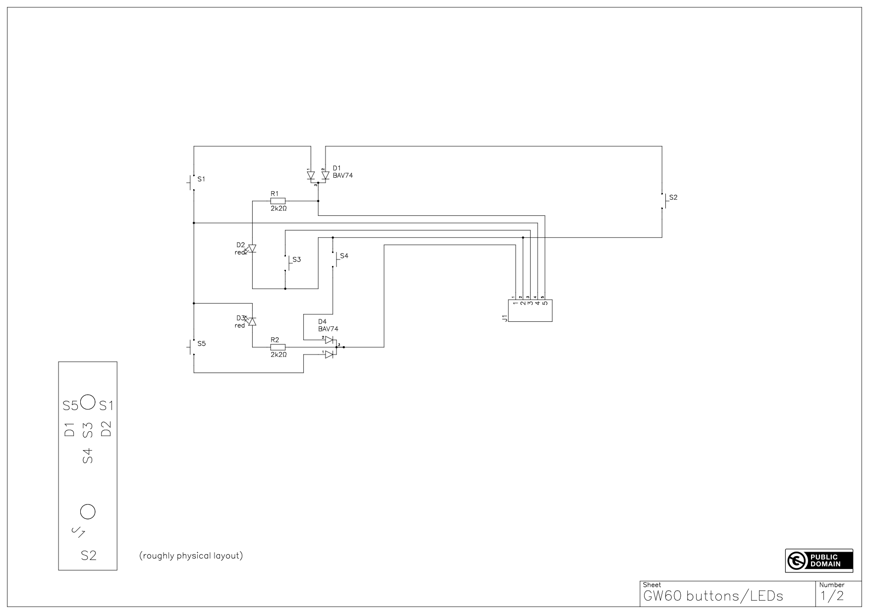
- the connector from the “main” PCB to the “buttons & LEDs” PCB should be Molex PicoBlade 51021 compatible. Haven’t verified that though. (Compatible connectors are made by a whole bunch of companies.)
All in all, I probably wouldn’t even bother reverse engineering this further, and just build a completely new PCB with an ESP32 (or other µC) on it. But here it is, in case it helps anyone.
Cheers!
(LED/button board in a separate post, “new users can only put one file”)