maybe… Sergey reply.
Hi all,
My idea was “Small dongle with minimum components and fully assembled by PCB manufacturing service in standard case”.
And I did it.

Now my AC is smart!


I have published project on github https://github.com/lizardsystems/midea-mini-dongle/ You may freely use this.
3 Likes
Any idea if this would work with the Mr. Cool AC units I believe that they are made by Midea? Mine has the WiFi module that plugs in.
Yup, it works just fine. Use ESP-01 to UART converter and ESP code shown in this thread
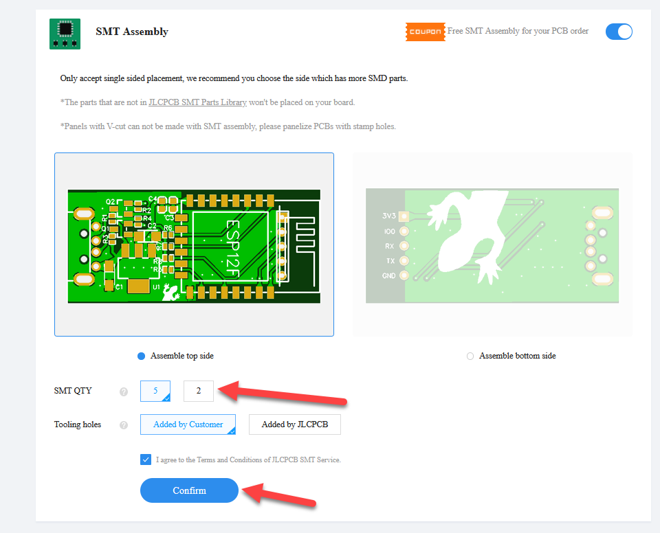
This looks great! I’d like to get one of these. How do I go about ordering from JLCPCB? I have never done something like this before. Could you point me to a guide showing what to do with the Gerber, BOM and CPL files?
Is there any list of confirmed working devices anywhere? Im about to procure a new AC but a bit unsure if new models will work or not using the awesome esphome integration


I am not aware off. But hey, let’s try make one! Who ever get this working - add your device to the list:
- MrCool Minisplit DIY MultiZone AC/Heatpump - models DIY-09-HP-WMAH-230B & DIY-12-HP-WMAH-230B (2020, USA market)
Great idea @mariojas and @yodi, I made a new thread so the valuable information isn’t lost somewhere in here.
You can find it here:
All others, please add your data to the new thread. I’ll post a request in the telegram group as well. ![]()
I updated from 1.18 to 1.19.4 and added preset_eco: true to my YAML. I was expecting the climate entity to update showing the ECO mode but it didn’t, and looking in the developer tools → state attributes this is what I’m seeing.
hvac_modes:
  - 'off'
  - heat_cool
  - cool
  - heat
  - fan_only
  - dry
min_temp: 64
max_temp: 86
target_temp_step: 1
fan_modes:
  - auto
  - low
  - medium
  - high
swing_modes:
  - 'off'
  - vertical
current_temperature: 69
temperature: 64
fan_mode: low
swing_mode: 'off'
friendly_name: Basement AC
supported_features: 41
No presets. I tried deleting and re-adding the integration and it didn’t seem to make a difference. Is this a problem on the ESPHome side or is this an issue with HA?
Where did you locate the special USB connector that the unit uses?
There are some people here, that just cut out the edges on their USB, see pic in this post. Some use a Dremel or a small scalpel to cut it out.
On the other hand, I’d advise against such a thing, as it seems way easier to just use cables (like the small jumper cables) and avoid the USB part altogether. Take a look at the pics in this thread and the different github repos.
That depends. I was just unplugging existing wifi module and pluging in mine. 1 minute with flat soldering iron did the trick.
Good idea! ![]()
![]()
Ah, thanks. I didn’t realize that would work. It looked like the pins didn’t line up at first glance.
1 Like
I think that’s only works when the wifi part is integrated into the mainboard, and it’s a no go when you have that intermediate part visible on the pic you linked.
Sorry, don’t know what you mean. 
The USB port on the unit is only a USB female with four cables going to a connector on the board. And what intermediate part do you mean?

This one (the intermediate part).
And it’s not possible to connect anythiny into the Female USB part, because of this.

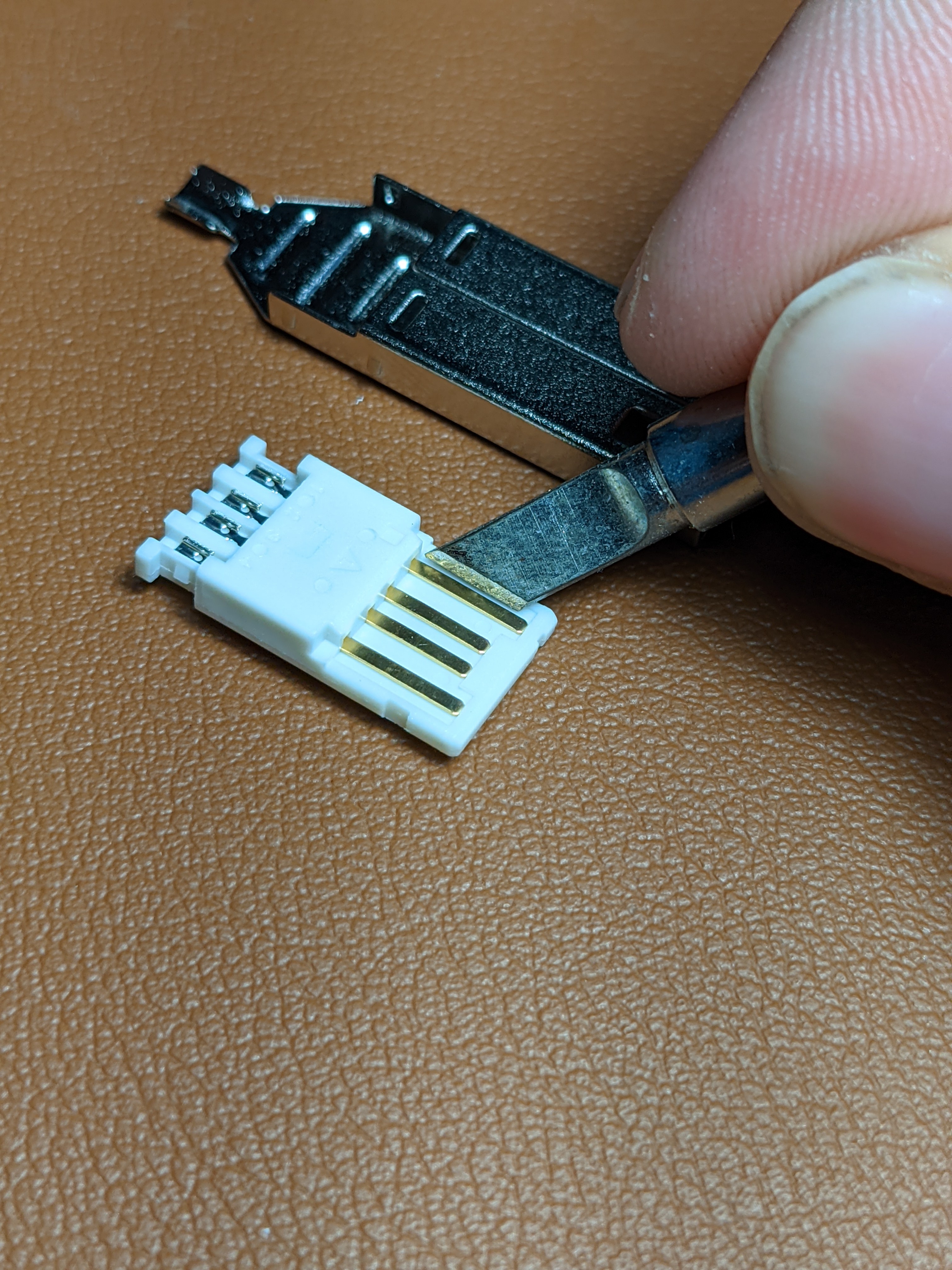
Yeah, that’s exactly what I am dealing with. I was reaching out to Mouser, but they don’t have them. I ended up using regular ones and modifying them. When you buy new usb plug you get it in pieces, including plastic insert. Pins lines up as they should, you just need to take off some plastic on the edges. I am using flat soldering iron and it works nicely.

1 Like
If you have that intermediate part, you’ll have to modify your USB plug, that’s true.
But you have a few different ways to do so:
- soldering iron to burn out (as @mariojas mentioned)
- scalpel to cut these out
- Dremel (or sanding paper) to sand out the unnecessary parts
- unsolder the USB port on the intermediate part and
- solder in a new connector (something like this)
- directly solder the cables from the ESP to the unsoldered connectors
1 Like