I’ve documented the protocol for the Resideo/Honeywell gas water heater valves. The work was done based on the WV8840 but also tested on the WV8860. The devices have a communications port on the bottom where you can query current state and enable/disable vacation mode.
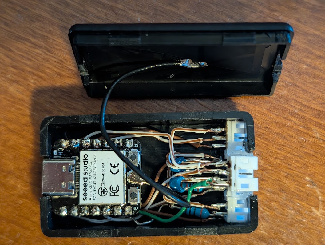
It includes an implementation based on ESPHome and the ESP32C3. The example implementation includes in addition to the communications port a water leak sensor, inlet/outlet temperature sensors, and a water flow sensor. The extra bells and whistles are not necessary of course, just the serial connection for the communications port.
Outstanding work @russ.dill .Thank you! Looking to implement this project.
How did you physically connect to the COM port on the underbelly of the board? Looks like I could spend 100 bucks on the Bradford White accessory module which has a cable that should work, but would rather find a cheaper solution.
It’s discussed in the PROTOCOL.md. If you can get a Lumberg RAST 2.5 3512 03, it’s a perfect fit, but those are difficult to source. I used a TE 1-2391423-3 and added a key to prevent reverse insertion with a very thin piece of plastic and some epoxy.
Found this after noticing the com port on my hot water tank controller. A Honeywell WV8840.
Looks like the Molex 093050-0001 connector would probably also fit.
Would it be possible to estimate gas consumption using the current state data?
If one could figure out the flow rate multiplied by how long the unit is firing?
This is awesome! I’m trying to make it work with this ESP32 board though and I’m having issues with the wiring. Could you possibly explain the connection to the RX of the WV8840? Or make a quick wiring diagram? I can see that I’m transmitting but never receiving anything back. Using pins 16 and 17, but do I need to add 3.3v power somewhere in the circuit?
Right now I am going ESP32 TX (GPIO17) > Resistor > Diode > Cap to GND > WV8840 RX
WV8840 TX > ESP32 RX (GPIO16)
GND > GND
It’s just a straight connection. The diode, cap and resistor are all on the WV8840 side. The RX line of the WV8840 is inverted so the idle state is high, and uses IRDA signalling so the pulses are short. This allows the line to provide power.
I have a WV8860C1000. It has the same RX, TX and GND on the board. I got a connector and put it on the honeywell board with wires and measure 3.4V on RX, 0V on TX at the Honeywell board.
I connect it to my Seeed Xiao esp32c3 chip - just like yours. A straight connection without any resistors or other electronics from pin 4 (GPIO4 set as uart_rx) to honeywell TX and pin 5 (GPIO5 set as uart_tx) to honeywell RX and GND to GND.
In my yaml I have set GPIO9 as the dummy_tx.
I just can’t get any return signal from the honeywell board. Does the Honeywell TX use power from the honeywell board to communicate to the esp32?
Any suggestions for testing or debugging? In your picture you have several resistors and capacitors but maybe those are for your other sensors/devices?
I can’t really see how you’ve connected your Xiao esp32c3 to the honeywell from the photo you posted.
Actually I just got it working. My problem was I had the wrong board type specified. It really was just a direct connection. I had bought all kinds of diodes and resistors and stuff. None of that was needed.
I too was able to get it to work by following what you said.
So to add the board PIN numbers to what you wrote: I connected on my Seeed Studio XIAO esp32-c3 board uart_tx: GPIO20 (pin D7) to the Honeywell board labeled RX. I connected pin D4 GPIO6 on the Xiao board to the center Honeywell board pin labeled TX.
I purchased these connectors Molex 0930500001 from DigiKey to make the connection to the Honeywell board. Digikey part number: 23-0930500001-ND
3CKT RAST APPLI MATE GWT MATERIA
3 Position Rectangular Receptacle Connector IDC Tin 22-24 AWG
Thanks so much for your help!
Here is my YAML
# Substitutions for the pins used in your Parallel Bridge
substitutions:
  uart_dummy_tx: GPIO21
  uart_tx: GPIO20
  uart_rx: GPIO6


esphome:
  name: water-heater-xiao
  friendly_name: "Water Heater XIAO"

esp32:
  board: seeed_xiao_esp32c3
  framework:
    type: esp-idf

logger:
  level: DEBUG

api:
  encryption:
    key: "redacted"

ota:
  - platform: esphome
    password: "redacted"

wifi:
  ssid: !secret wifi_ssid
  password: !secret wifi_password
  ap:
    ssid: "Water Heater Fallback"
    password: "redacted"

captive_portal:

# This pulls in the specific C3 hardware config and the heater logic
packages:
  remote_package:
    url: https://github.com/russdill/resideo
    ref: main
    refresh: 5min
    files:
      - packages/modbus-esp32c3.yaml
      - packages/wv8840c-modbus.yaml
The tank temperature reading kind of sucks. It drops really quick, which I imagine is because of the sensor placement so that the tank starts heating as soon as you use a little bit of hot water. I’m probably going to place some temp sensors on the cold and hot water pipes going to the top of the tank.
The really interesting thing about the internal temperature sensor is that after heating turns off if there is no water flow, it continues to rise for a very long time on the order of dozens of hours. There must be some effect of the water becoming very stratified. An “interesting” effect of this is that if you don’t use the water for several days the heat doesn’t run, but the temperature of the water coming out will be much higher than set point, to the point of possibly scalding.
It worked on the first try! I used ESP32-C3 Super Mini board for $4, Molex 0930500001 connector and UART configuration posted by @dsmithut. Awesome project. Thank you @russ.dill!
I’m seeing occasional protocol timeout errors in the logs and the status is dropping to offline intermittently. Is this expected?
[18:46:38.527][D][modbus_controller.sensor:025]: Sensor new state: 100.00
[18:46:38.531][D][sensor:124]: 'Temperature Hysteresis' >> 10.0 °F
[18:46:38.535][D][modbus_controller.sensor:025]: Sensor new state: 1250.00
[18:46:38.539][D][sensor:124]: 'Last Temperature Setting' >> 125.0 °F
[18:46:38.543][D][modbus_controller.sensor:025]: Sensor new state: 100.00
[18:46:38.547][D][sensor:124]: 'Last Temperature Hysteresis' >> 10.0 °F
[18:46:38.551][D][modbus_controller.sensor:025]: Sensor new state: 1215.00
[18:46:38.555][D][sensor:124]: 'Unknown (0x000e)' >> 1215
[18:46:46.146][D][uart_debug:113]: >>> 7F:04:04:4C:00:01:FB:33
[18:46:46.431][W][modbus:064]: Stop waiting for response from 127 301ms after last send
[18:46:46.478][W][modbus:263]: Ignoring response - not expecting a response from 127, 348ms after last send
[18:46:46.650][D][uart_debug:113]: >>> 7F:04:04:4C:00:01:FB:33
[18:46:46.935][W][modbus:064]: Stop waiting for response from 127 301ms after last send
[18:46:46.998][W][modbus:263]: Ignoring response - not expecting a response from 127, 364ms after last send
[18:46:47.153][D][uart_debug:113]: >>> 7F:04:04:4C:00:01:FB:33
[18:46:47.438][W][modbus:064]: Stop waiting for response from 127 301ms after last send
[18:46:47.513][W][modbus:263]: Ignoring response - not expecting a response from 127, 376ms after last send
[18:46:47.644][W][modbus_controller:027]: Modbus device=127 set offline
[18:46:47.649][D][text_sensor:120]: 'Status' >> 'Offline'
[18:46:47.652][D][modbus_controller:039]: Modbus command to device=127 register=0x2A88 no response received - removed from send queue
[18:46:47.670][D][uart_debug:113]: >>> 7F:04:04:00:00:02:7A:E5
[18:46:47.956][W][modbus:064]: Stop waiting for response from 127 301ms after last send
[18:46:48.046][W][modbus:263]: Ignoring response - not expecting a response from 127, 390ms after last send
[18:46:48.185][D][uart_debug:113]: >>> 7F:04:04:00:00:02:7A:E5
[18:46:48.302][W][modbus_controller:069]: Modbus device=127 back online
[18:46:48.314][D][text_sensor:120]: 'Last Major Problem' >> ''
[18:46:48.691][D][uart_debug:113]: >>> 7F:04:00:08:00:01:BA:16
[18:46:48.818][D][modbus_controller.sensor:025]: Sensor new state: 0.00
[18:46:48.820][D][sensor:124]: 'Unknown (0x0008)' >> 0
[18:46:49.211][D][uart_debug:113]: >>> 7F:04:00:00:00:08:FB:D2
[18:46:49.399][D][modbus_controller.sensor:025]: Sensor new state: 3690.88
[18:46:49.403][D][sensor:124]: 'NTC right raw reading' >> 3691 Ω
[18:46:49.407][D][modbus_controller.sensor:025]: Sensor new state: 3706.52
[18:46:49.411][D][sensor:124]: 'NTC left raw reading' >> 3707 Ω
[18:46:49.415][D][modbus_controller.sensor:025]: Sensor new state: 1202.00
[18:46:49.419][D][sensor:124]: 'NTC Raw Temperature' >> 120.2 °F
[18:46:49.423][D][modbus_controller.sensor:025]: Sensor new state: 1216.00
[18:46:49.427][D][modbus_controller.sensor:025]: Sensor new state: 740.00
[18:46:49.431][D][modbus_controller.sensor:025]: Sensor new state: 125.00
[18:46:49.434][D][sensor:124]: 'Temperature Control Setting' >> 125.0 °F
[18:46:49.439][D][text_sensor:120]: 'Problem' >> 'None'
[18:46:49.442][D][text_sensor:120]: 'Status' >> 'Idle'