Tasmota and LED Wifi Controller Help

Would anyone be able to offer advise on which Sonoff “Module Type” I should use for a CCT (cool/warm white) LED controller with Tasmota firmware please?
image

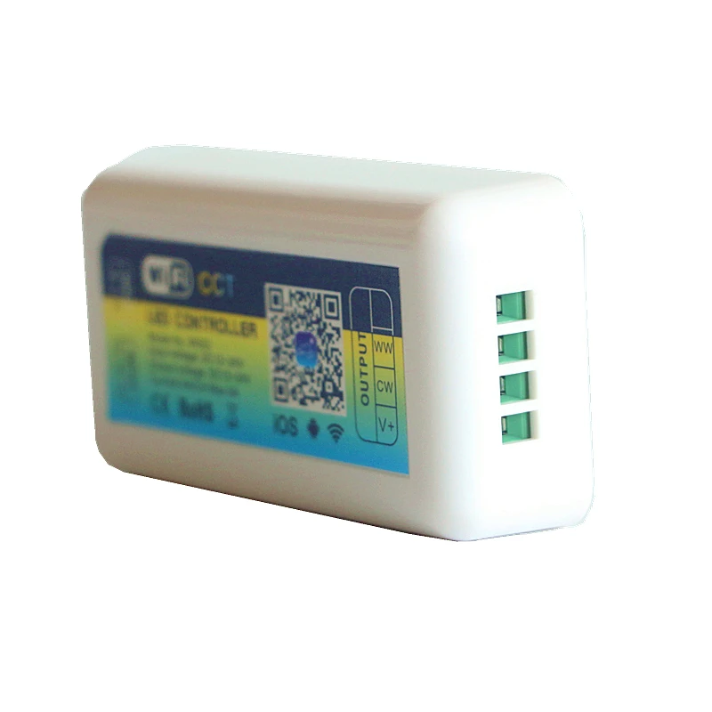
I’m using the CCT version of this WiFi Smart LED Controller (shown below) which has a page on the Tasmota Wiki showing pinouts for flashing. I have successfully uploaded the Sonoff.bin firmware to the module, but I haven’t had any luck controlling an LED strip with it so far. I can’t even turn it on and off via the Tasmota web interface, let alone control it via HA.

I suspect that there’s no official Module for this controller which would be a real shame given that its a great, cheap wifi controller, ideal for use with HA/MQTT.

Thanks in advance!

Pretty sure your wiring is wrong. Black should be on the left, and the other two in the next two slots. There is a large picture on the Aliexpress page and the order is (from the left)

V+ CW WW NC

Hi @nickrout, thanks for your help.

I realise it isn’t the best of pictures to see what’s happening with the wiring, but I can confirm they are wired correctly. If you were to turn the controller with the wires over, and then turn the 2nd unit below around by 180 degrees, you would see the wiring match up (i’ll go take a photo in a sec).

I have now been able to turn it on and off when using “01 Sonoff Basic”, but the lights are on when the webpage says off, and the lights go off when toggled to On. :slight_smile:

“26 Sonoff B1” just causes the lights to flicker

“29 Sonoff T1 2CH” gives me two toggle switches, it both just turn on the warm leds.

I’m going to keep on researching this as I really want to get it working.

In case it helps anyone else trying these wifi modules out, I figured out the following combination of GPIO and PWM channels allows me to swap between warm and cool white, along with overall dimming of the lights.

The GPIO pin choice is based on the labels found in this image:

Next task is to figure out the YAML based on the examples found here. I’ll report back once I have a working solution.

To finish this off for future reference, I configured the light in HA with the following yaml:

light:
  - platform: mqtt
    name: "sonoff_wifi_ctrl_1"
    command_topic: "cmnd/sonoff_wifi_ctrl_1/POWER"
    state_topic: "tele/sonoff_wifi_ctrl_1/STATE"
    state_value_template: "{{value_json.POWER}}"
    availability_topic: "tele/sonoff_wifi_ctrl_1/LWT"
    brightness_command_topic: "cmnd/sonoff_wifi_ctrl_1/Dimmer"
    brightness_state_topic: "tele/sonoff_wifi_ctrl_1/STATE"
    brightness_scale: 100
    on_command_type: "brightness"
    brightness_value_template: "{{value_json.Dimmer}}"
    color_temp_command_topic: "cmnd/sonoff_wifi_ctrl_1/CT"
    color_temp_state_topic: "tele/sonoff_wifi_ctrl_1/STATE"
    color_temp_value_template: "{{value_json.CT}}"
    effect_command_topic: "cmnd/sonoff_wifi_ctrl_1/Scheme"
    effect_state_topic: "tele/sonoff_wifi_ctrl_1/STATE"
    effect_value_template: "{{value_json.Scheme}}"
    effect_list:
      - 0
      - 1
      - 2
      - 3
      - 4
    payload_on: "ON"
    payload_off: "OFF"
    payload_available: "Online"
    payload_not_available: "Offline"
    qos: 1
    retain: false

You can test it within Services using this:
image

Then control it in automations using:

action:
  service: light.turn_on
  data:
    entity_id: light.sonoff_wifi_ctrl_1
    brightness: 10
    color_temp: 200

FYI, I’m using the 24V version of the following LED strip:
Color Temperature Pure White+Warm White Series DC12V 5050SMD 300LEDs 2in1 Flexible LED Strip Lights
Along with this PSU:
Mean Well LRS-150-24 DC24V 150Watt 6.3A UL Certification AC110-220 Volt Switching Power Supply For LED Strip Lights

1 Like

Hello there!
@jarrah

I´ve been looking all over for this exact config, but lacked de CCT topic!

Thanks a lot for posting this. Can you post a picture of how it shows on HA?

Hello!

I know this is an older thread but i could not find anything for the RGBW Model of this exact controller.

If someone bought the same controller as I did (the RGBW Model) here are the working setting and template to use:

{"NAME":"*yourname","GPIO":[0,0,0,0,0,0,0,0,38,39,37,40,0],"FLAG":0,"BASE":18}

For this template you only have to reset the RGBWW Table with the following command:

RGBWWTable 255,255,255,255,255

and you are ready to go!

If you are using the RGB+CCT version of this controller, just find out what GPIO is used for the other white PWM output. I used the ID Relays template:

{"NAME":"ID Relays","GPIO":[0,0,0,0,21,22,0,0,23,24,25,26,27],"FLAG":0,"BASE":18}

greetings