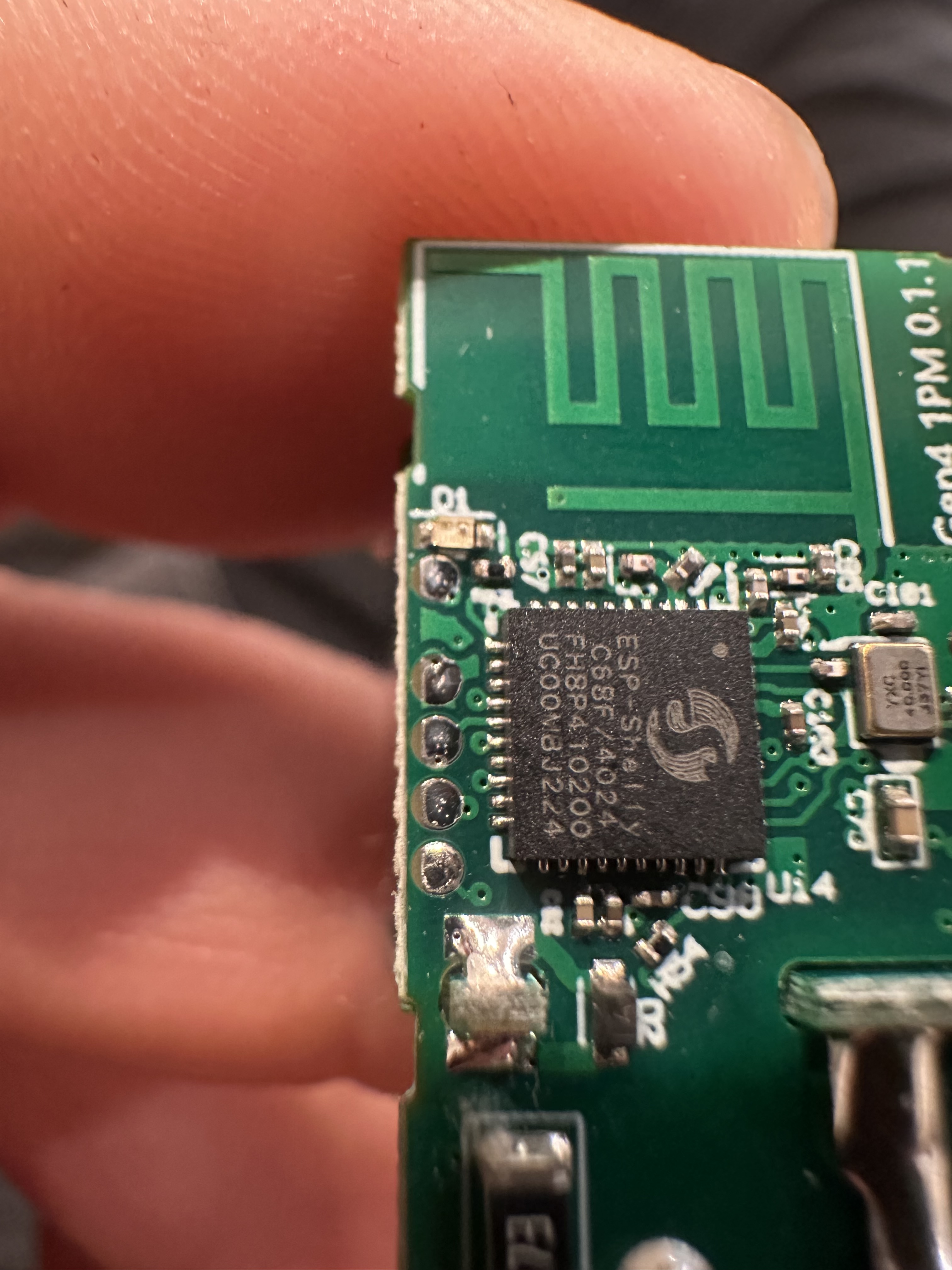
Has anyone tried ESPHome on a Shelly 1 Gen4? Did the OpenThread component work?
It has a chip ESP-Shelly-C68F, a variant of ESP32-C6 with more memory. The Shelly firmware does not support Thread.
Has anyone tried ESPHome on a Shelly 1 Gen4? Did the OpenThread component work?
It has a chip ESP-Shelly-C68F, a variant of ESP32-C6 with more memory. The Shelly firmware does not support Thread.
What messages do you get?
Are you using the ESP-IDF, and not Arduino?
I have tried this with the 1/2PM Gen4. For the regular Shelly 1 Gen4 there is no existing ESPHome config / pinout available and in this regard it is not similar to other devices.
The OpenThread integration is extremely simple:
# You need to disable wifi
# wifi:
#  ssid: !secret wifi_ssid
#  password: !secret wifi_password

network:
  enable_ipv6: True

openthread:
  tlv: # Copy from Settings -> Integrations -> Thread -> Info -> Active dataset TLVs
Everything else basically works out of the box and you can switch back and forth between Thread and WLAN using OTA updates. There should be no difference for the Shelly 1 Gen4, all of these models use the same microcontroller.
However, I also made power measurements while testing. The idle values were ~0.6W for WLAN and ~1W for Thread. I had no success in making it more efficient using the existing options. Thus, I can only recommend Thread in case you want to reduce the traffic on your WLAN channel.
Thanks. How did you first flash the Shelly with ESPHome?
The usual way, with a USB to serial port?
Any tutorial to follow step-by-step?
Gimme a minute while I search. First Espessif, then Shelly, then ESPHome, and then the forums here.
nice to know. i am considering the same, using a new shelly with thread.
main goal would be using the shelly addon to be able to connect sensors while beeing powered with 240V.
It would be nice to see all process on YouTube or screen shots, it help a lot for people who is searching Matter over Thread relay. If it works flawlessly, then it solve thousands of people problem and make stronger inner thread mesh network.
I have no experience with ESPHOME, neither OTA FLASHING, but if I got some time to play with it, I will try to learn and after all document it to help others, but need some advisor if something goes wrong 
First hard step is flashing shelly over the serial connection as OTA is unlikely to work.
I did it once and struggle to repeat the process right now.
First thing i would try then is to make a backup of the original firmware.
If i succeed i plan to document it 
I disassembled and spent all evening to try flash it. As first timer, unsuccessfully…
The pins on left side of pcb I tried from top:
Reset
3.3V
TX
Rx
gpio9/boot
Im sure that reset is first, when short with GND in the middle on top (WHICH I find with multimeter), it restarts two times Rx and Tx led blinks on the USB-TTL FT232 converter.
I tried to short gpio9boot +GND, then with button - haven’t received any success. As a first timer, it can be due to many other flaws in process. Maybe someone can help me and ensure that I discovered those contacts accurately?
I finally got to backup and flash my Shelly 1 Gen4 successfully with ESPhome.
I had to modify my USB serial flasher with an additional GND pin to connect the IO-0 to GND in order to activate flash mode.
ESP home basic is running via WiFi, right now i try to get the sensor addon running. Last step will be switching from wifi to thread.
If successful i am happy to write a documentation
Is this a Shelly Mini?
Look similiar to gen3:
Yes, it’s shelly 1pm mini gen4 (detailed json below). It seems similar, but missing GND, WHICH I find during testing brown capacitors I’m not sure that others is correct too, first time with pcb flashing, many places go wrong 
{“name”:null,“id”:“shelly1pmminig4-7c2c6779d80c”,“mac”:“7C2C6779D80C”,“slot”:0,“model”:“S4SW-001P8EU”,“gen”:4,“fw_id”:“20250214-121727/1.5.99-g4prod1-gc32c24b”,“ver”:“1.5.99-g4prod1”,“app”:“Mini1PMG4”,“auth_en”:false,“auth_domain”:null,“matter”:true}
Getting the Shelly 1 Gen4 connecting with opnthread was easy.
Right now im trying to figure out the GIPO configs as they dont match the Shelly 1/2PM Gen4.
Any idea of how to get the pin mapping?