Hi,
Just to share my code / idea.
I am going to use an actuator to open and close a latch. The actuator does not have position control, just a limit switch on one side to make sure it does not break things.
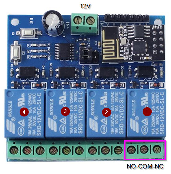
The board I am using, uses ESP8266-01 (ESP-01) together with 4ch relay (12V version) and it is communicating through UART. I choose this board because it uses 12V, just as the actuator.
Of course there are other options available to drive a motor/actuator.
The board will operate (open/close) the actuator by putting 12V on it. To reverse the action, the polarity needs te be reversed.
I have it working currently. (But I am going to rebuild it into a slightly different version which also alows extra manual buttons to open close instead of using ESPHome only.
To note: keep in mind this solution IS a software based solution. In theory, Despite being programmed into the ESP chip. It can happen that one of the relays fails or stick and report an incorrect state, thuis causing a short circuit. Although realisticly I would guess the chances of this happening are very very slim / neglectable. I would use it regardless. But he best possible solution is to use DPST relay. But I dont have one spare.
Hardware I use::
-
4Ch relay board. >link<
-
12V adapter for powering the motor + the relay board. Any adapter capable of supplying the amps will do. I use a 36W version.
I am using the relays as following:
- Control relay
- Power relay
- Output 1
- Output 2
Relay 1, the control relay. This is the relay which acts as a trigger and is programmed to trigger relay 2, 3 and 4 in specific sequences. Operating relay 1 can be done through HomeAssistant or NodeRed or MQTT etc.
I do NOT want relays 3+4 to be directly manipulated. Human error >> short circuit.
Relay 2, the power relay. I use this one to take off power to the drive, switch and put power back on. There are conditions to check befor turning power on, that both outputs are in correct possitions. If not, it will not switch. This relay can be operated from outside without harm.
Relay 3 + 4 are the output relays which connect to the motor/actuator.
In these two relays I have put conditions to ONLY switch when relay 2 is OFF.
These relays are ‘hidden’ to prevent manual operation (“internal: true”)
Diagram looks like this:

Ofcourse in the image, the wire colors are incorrect, but it shows well enough.
ESP code
Of course I flashed the ESP-01 (ESP8266) with ESPHome. Took it off the board, and flashed it directly.
esphome:
  name: esp01relay
  platform: ESP8266
  board: esp01_1m

wifi:
  ssid: "your_ssid"
  password: "your_password"
  manual_ip: # optional
    static_ip: 192.168.4.xx # optional
    gateway: 192.168.4.1 # optional
    subnet: 255.255.255.0 # optional

# Enable logging
logger:

# Enable Home Assistant API
api:
  password: "your_password"

ota:
#  password: "your_password"

mqtt:
  broker: 192.168.4.xx
  username: "your_username"
  password: "your_password"

# Sensors with general information. Nice to have
sensor:
  # Uptime sensor.
  - platform: uptime
    name: Relay Uptime

#  # WiFi Signal sensor.
#  - platform: wifi_signal
#    name: Relay WiFi Signal
#    update_interval: 60s

uart: # Defines the communication to the relayboard
  baud_rate: 115200 # speed to STC15L101EW
  tx_pin: GPIO1
  rx_pin: GPIO3

#------------------------------------------------------------------------------
#------------------------------------------------------------------------------
# reference commands for switches on relay board!
#      - uart.write: [0xA0, 0x01, 0x01, 0xA2] # 1 ON CONTROL SWITCH
#      - uart.write: [0xA0, 0x01, 0x00, 0xA1] # 1 OFF CONTROL SWITCH
#
#      - uart.write: [0xA0, 0x02, 0x01, 0xA3] # 2 ON ACTUATOR POWER
#      - uart.write: [0xA0, 0x02, 0x00, 0xA2] # 2 OFF ACTUATOR POWER
#
#      - uart.write: [0xA0, 0x03, 0x01, 0xA4] # 3 ON REVERSE POLARITY NEGATIVE
#      - uart.write: [0xA0, 0x03, 0x00, 0xA3] # 3 OFF REVERSE POLARITY NEGATIVE
#
#      - uart.write: [0xA0, 0x04, 0x01, 0xA5] # 4 ON REVERSE POLARITY POSITIVE
#      - uart.write: [0xA0, 0x04, 0x00, 0xA4] # 4 OFFREVERSE POLARITY POSITIVE
#------------------------------------------------------------------------------
#------------------------------------------------------------------------------

switch: # Optional extra switch to restart the board.
  - platform: restart
    name: esp01relay-restart
    id: restart_switch

#------------------------------------------------------------------------------
# Relay 1: This relay is used to controll all other relays.
# The sequence of switching is defined here.
  - platform: template
    name: 'Relay 1' # CONTROL SWITCH
    id: relay1
    turn_on_action:
      - switch.turn_off: relay2
      - delay: 20ms
      - switch.turn_on: relay3
      - delay: 20ms
      - switch.turn_on: relay4
      - delay: 50ms
      - switch.turn_on: relay2
      - delay: 20ms
      - uart.write: [0xA0, 0x01, 0x01, 0xA2] # 1 ON
    turn_off_action:
      - switch.turn_off: relay2
      - delay: 20ms
      - switch.turn_off: relay3
      - delay: 20ms
      - switch.turn_off: relay4
      - delay: 50ms
      - switch.turn_on: relay2
      - delay: 20ms
      - uart.write: [0xA0, 0x01, 0x00, 0xA1] # 1 OFF
    optimistic: true

#------------------------------------------------------------------------------
# Relay 2: This relay is used to actually put power on the circuit.
# There are conditions here to make sure switches 3 and 4 are in the right position.
# Otherwise the switching will NOT take place.
  - platform: template
    name: 'Relay 2' # SWITCH ACTUATOR POWER
    id: relay2
    optimistic: true
    on_turn_on:
      if:
        condition:
          or:
            - and:
              - switch.is_off: relay3
              - switch.is_off: relay4
            - and:
              - switch.is_on: relay3
              - switch.is_on: relay4
        then:
          uart.write: [0xA0, 0x02, 0x01, 0xA3] # 2 ON ACTUATOR POWER
    on_turn_off:
      - uart.write: [0xA0, 0x02, 0x00, 0xA2] # 2 OFF ACTUATOR POWER

#------------------------------------------------------------------------------
# Relay 3: This relay is part 1 to flip polarity on the actuator
# Condition is that it will ONLY switch when relay 2 is off (Relay 3 and 4 are not live).
# This condition stops direct manual switching and prevents short circuit.
  - platform: template
    internal: true # HIDE SWITCH FROM DASHBOARDS (OPTIONAL)
    name: 'Relay 3' # ON/OFF REVERSE POLARITY NEGATIVE
    id: relay3
    turn_on_action:
      if:
        condition:
          - switch.is_off: relay2
        then:
          - uart.write: [0xA0, 0x03, 0x01, 0xA4] # 3 ON
    turn_off_action:
      if:
        condition:
          - switch.is_off: relay2
        then:
          - uart.write: [0xA0, 0x03, 0x00, 0xA3] # 3 OFF
    optimistic: true

#------------------------------------------------------------------------------
# Relay 4: This relay is part 2 to flip polarity on the actuator
# Condition is that it will ONLY switch when relay 2 is off (Relay 3 and 4 are not live).
# This condition stops direct manual switching and prevents short circuit.
  - platform: template
    internal: true # HIDE SWITCH FROM DASHBOARDS (OPTIONAL)
    name: 'Relay 4' # ON/OFF REVERSE POLARITY POSITIVE
    id: relay4
    turn_on_action:
      if:
        condition:
          - switch.is_off: relay2
        then:
          - uart.write: [0xA0, 0x04, 0x01, 0xA5] # 4 ON
    turn_off_action:
      if:
        condition:
          - switch.is_off: relay2
        then:
          - uart.write: [0xA0, 0x04, 0x00, 0xA4] # 4 OFF
    optimistic: true

#------------------------------------------------------------------------------
Regarding the board. Be sure to use “esp01_1m” as a board. I think all black pcb’s are the 1M versions.
The “esp01” = 512kb (blue pcb version) which does not allow enough lines. OTA stops working soon then.
I hope by putting this up here I might help someone.
[edit] Just corrected code part