Hey everyone,
I’m relatively new to the scene and don’t have much experience with electronics and programming, but I’m currently working on a project that involves an ESP32 microcontroller, a specific pinout configuration, and a power meter. However, I’ve encountered an issue and could really use some guidance. Here’s what I have:
-
ESP32 with the following pinout: ESP32_DevKit_C_V4_Pinout.pdf (shopify.com)
-
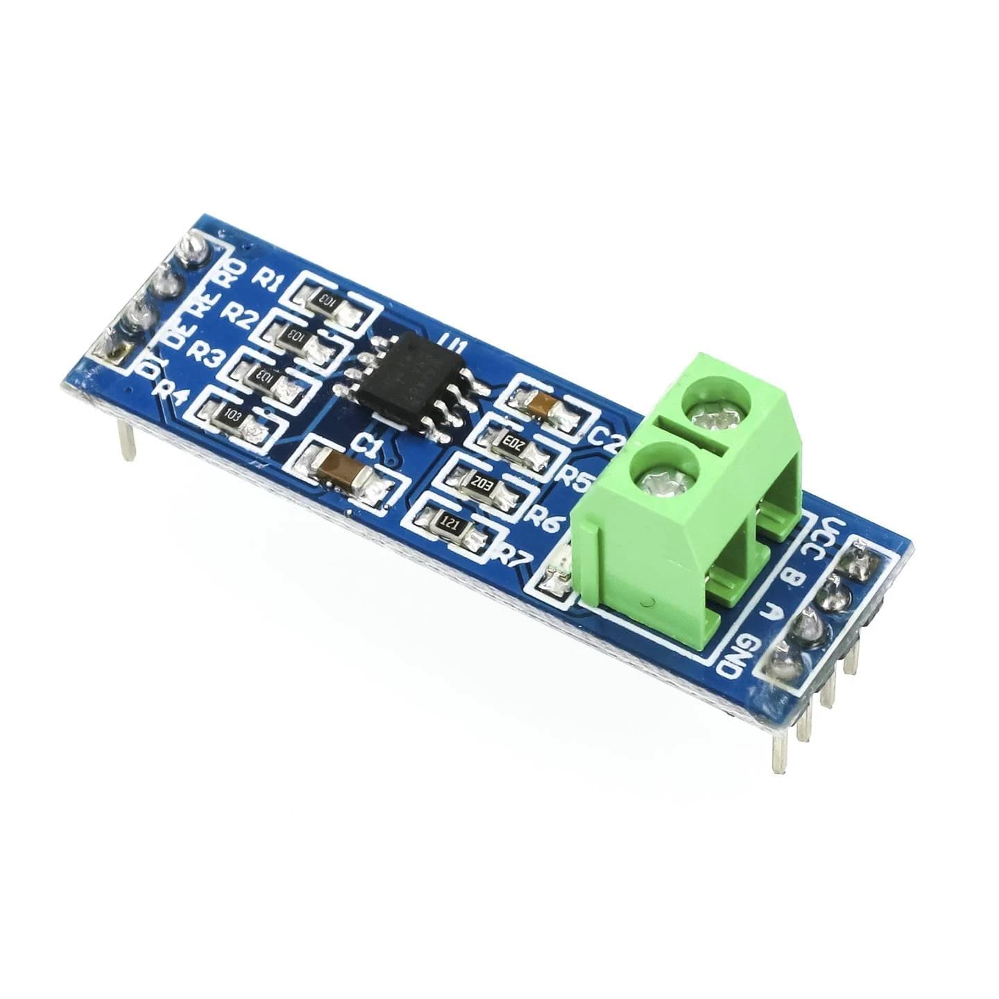
A power meter with the instructions available here: Eastron SDM220M* User Manual (xn–stromzhler-v5a.eu) an TTL to RS485 module:
-
I have wired everything according to this diagram (of course the ESP and the power meter are connected to power supply):

In my ESPHome configuration, I have the following code for this setup:
esphome:
  name: rs485
  friendly_name: Rs485

esp32:
  board: esp32dev
  framework:
    type: arduino

# Enable logging
logger:
  baud_rate: 0

uart:
  id: mod_bus
  tx_pin: GPIO1
  rx_pin: GPIO3
  baud_rate: 9600
  stop_bits: 2

modbus:
  flow_control_pin: GPIO0
  id: modbus1

modbus_controller:
  - id: controller
    ## the Modbus device addr
    address: 0x1
    modbus_id: modbus1

sensor:
  - platform: modbus_controller
    modbus_controller_id: controller
    name: "Currents sum"
    id: currents_sum
    address: 30049
    register_type: holding
    value_type: U_DWORD
    unit_of_measurement: "A"


# Enable Home Assistant API
api:
  encryption:
    key: "P/LTB5girwA0bT84O0lL7bLzGszImPRhWTBNQaSTeIs="

ota:
  password: "410734d9197a1988aea69177ccb0269c"

wifi:
  ssid: !secret wifi_ssid
  password: !secret wifi_password

  # Enable fallback hotspot (captive portal) in case wifi connection fails
  ap:
    ssid: "Rs485 Fallback Hotspot"
    password: "lRKwYkASr0kA"

captive_portal:
However, when I check the logs, I see the following error message:
[D][modbus_controller:032]: Modbus command to device=1 register=0x1683 countdown=0 no response received - removed from send queue
Additionally, the entity associated with the power meter shows a status of “Unknown.”
I’m trying to figure out what I might be doing wrong here. Any tips or suggestions would be greatly appreciated. Thank you in advance!
Best regards, Felix

