I have an m5 atom lite and an m5 infrared emitter & receiver (as below)
I’ve configured this using the details found in esphome doco, and setting the gpio pin as per the m5 docs.
remote_receiver:
  pin:
    number: GPIO36
#    inverted: true
  dump: all
however nothing gets dumped.
I’ve tried:
using a different atom
using a different cable between the atom grove connector and the ir module
plugging a different sensor module into this atom to prove that the grove connector works
trying different GPIO settings, invert = true etc.
using multiple different remotes pointed at the receiver
configuring the i2c node for the grove bus to scan, however this caused errors to be logged
and haven’t been able to get anything reliably logged. At one stage, using a completely different GPIO (but something I saw on a forum) I got 1 or 2 IR received messages logged, but I assume given the nature of the codes, and the fact that it wasn’t actually configured correctly that these were just some kind of noise.
I’m wondering if I’m just missing something really simple, or whether I’ve got a dodgy IR emitter/receive unit and need to go back to m5/order another.
it mentions GPIO36 - Receiver pin. I’ve also seen a few blogs that indicate GPIO 36… one guy actually talked about GPIO32 in the text of his blog, but in the code he had GPIO36…
however I have tried GPIO 32 - it’s been a few days, will just try again.
Oh… so frustrating. So it works. I changed to GPIO32, and on boot I get the following warning, however it works:
[11:21:10][W][remote_receiver.esp32:058]: Remote Receiver Signal starts with a HIGH value. Usually this means you have to invert the signal using 'inverted: True' in the pin schema!
well thanks for your help @nickrout - apologies for wasting your time, but thanks for resolving the issue
Yes, the controller devices from M5Stack come in several different “families”. I haven’t worked with M5Stack’s “Stick”, “Core”, or “Stamp” families, so I don’t know how they use Grove connectors on those units. --from pic above, it looks like Core series uses “Port A” conventions (for I2C devices).
I do have several different models of the M5Stack “Atom” series (Atom Lite, AtomU, Atom Echo, Atom Speaker). I’ve found all of the Atom series use the same pinouts, in what would be considered “Type B” (generic IO).
As noted in the above link, M5Stack designates “Port A” usage for I2C, “Port B” for generic GPIO digital or analog IO, and “Port C” for UART usage. It really just depends on how you’ve programmed GPIO pin “X” --and whether pin “X” is supported by ESP32 for desired usage.
I’ve had success with routing different GPIO signals into the two Grove signal pins, using Grove-to-Dupont cables, just being careful to honor the ESP32 usages of those 2 pins. Or of course just connect directly to Dupont connectors on the Atom.
Good reference on Grove connector system is at: Grove System - Seeed Wiki
They describe the different types of usage, but not with same “Port x” labels that M5Stack uses (as mentioned in the above link).
I really like the M5Stack devices, because they provide enclosed cases that can just be plugged together. I could really see it for educational purposes, for people to do programming without getting caught up in hardware issues. Or for those of us not mechanically inclined, to avoid soldering and case building and such. It’s just unfortunate that they’ve broken some of the simplicity with this Type A/B/C stuff on the connectors. Oh well.
Tbh @Tobster77 I got it working after the advice above, but haven’t come back to actually implementing it. For my main use I bought a broadlink, but wanted to use this for a kitchen TV off/On, but the pain hasn’t got to the point of motivating me to implement it.
Will let you know if I come back to it and have success, cos I’d probably be after 3m range or similar.
Thanks. Note, I only get extremely low working distances (something like 10cm to 1m) to get reliable IR transmissions. Don’t know why the transmit power of the M5 IR sender is so extremely weak…
I finally dug it out again from the pile of stuff on my desk, checked the configuration, and remembered I had it configured to turn on an LED strip I have in my study. I plugged it in, put the IR transmitter as far from the led strip remote receiver as I could, and could turn it on. This was a distance of around 3.2 metres.
The built-in IR port in the Atom also works to approx 3.5 meters too?
To work out what PINs you need to map on the Atom Lite, you just need to look at them on the back (Reference picture that @nickrout posted works too) , and trace them (color wise) to the unit. It’s always going to be G26 or G32 for the Atom Lite.
The IR Remote then has In on the white cable and Out on the yellow.
@Chilling_Silence: Fully agreed! This is what logically makes sense. However, I had no chance to get the device working with this approach: I had to flip the role of the pins. This is the code that works ( with extremely low range):
esphome:
  name: "espatom-ir-blaster-1"

esp32:
  board: m5stack-core-esp32
  framework:
    type: arduino

# Enable logging
logger:

# Enable Home Assistant API
api:

ota:


wifi:
  ssid: !secret wifi_ssid
  password: !secret wifi_password

  # Enable fallback hotspot (captive portal) in case wifi connection fails
  ap:
    ssid: "Esphome-Web-Bfae70"
    password: "Kl4VccLdUcAF"

captive_portal:

remote_receiver:
  pin:
    number: GPIO32
    inverted: true
  dump: all


remote_transmitter:
  pin: GPIO26
  carrier_duty_percent: 50%

climate:
  - platform: heatpumpir       # adjust to match your AC unit!
    protocol: panasonic_dke
    name: "Bedroom AC"
    horizontal_default: mleft
    vertical_default: up
    max_temperature: 25
    min_temperature: 16
It wont “dump” stuff unless you shoot an IR remote at it to collect the data.
This works with the m5atom lite and the ir module. It puts a templated AC device into HA. The only thing that sucks/i havent figured out is how to add an external temp/humidity sensor to the AC template.
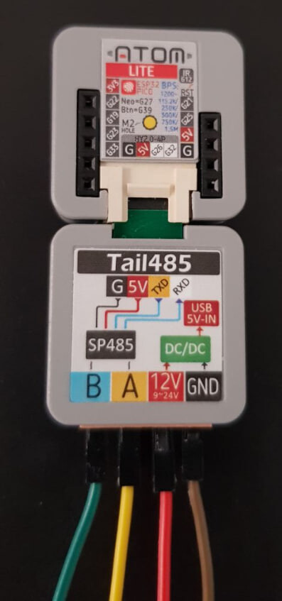
And you were correct. I use the Atom Lite with the Tail485 to control my pool chlorinator via RS485+Modbus. At first I was a bit lost with the tx/rx pinout, then I checked the Tail485 docs: m5-docs
You can see that on the top colored row, they show the pinout of the Atom to which you plug the Tail485, and the yellow pin (G26) is TX. The white (G32) is RX.
If you scroll the doc page, you’ll also find the Pin map, that confirms the interpretation: