I want to integrate DYP-A128NYTW-V1.0 this ultrasonic sensor to esphome. There no information on this sensor online just its datasheet. https://www.dypcn.com/uploads/A12-Datasheet.pdf.
I’m not sure what byte you need to send to get the distance, but to “decode” the output is the same I used here:
I’m new to this, can you help me implementing this.
Create a new device in Epshome:
esphome:
  name: dyp
  includes:
    - AJ_SR04M_Sensor.h

esp32:
  board: esp32dev
  framework:
    type: arduino

# Enable logging
logger:

# Enable Home Assistant API
api:
  encryption:
    key: "c62/j98uSjnmvNtgCc8hXyONiKy/A7NwYidIF0tXGiU="

ota:
  password: "abbc3b522d88a1dbba3455e98e594a38"

wifi:
  ssid: !secret wifi_ssid
  password: !secret wifi_password

  # Enable fallback hotspot (captive portal) in case wifi connection fails
  ap:
    ssid: "Dyp Fallback Hotspot"
    password: "ifnOKjB1NEzP"

captive_portal:


uart:
  id: uart_bus
  tx_pin: GPIO17 # Connect to DYP RX
  rx_pin: GPIO16 # Connect to DYP TX

  baud_rate: 9600
  stop_bits: 1
  rx_buffer_size: 4

sensor:
  - platform: custom
    lambda: |-
      auto my_sensor = new AJ_SR04M_Sensor(id(uart_bus));
      App.register_component(my_sensor);
      return {my_sensor};
    sensors:
      unit_of_measurement: cm
      accuracy_decimals: 2
      name: "Distance"
Create an AJ_SR04M_Sensor.h file inside the config/esphome folder
#include "esphome.h"

class AJ_SR04M_Sensor : public PollingComponent, public UARTDevice, public Sensor {
  public:

    AJ_SR04M_Sensor(UARTComponent *parent) : PollingComponent(1000), UARTDevice(parent) {}

    void update() override {

      byte frame[5];
      int pos = 0;
      float value = 0.0;

      //write(0x00); // Try this
      write(0x55); // Try this
      //write(0x01); // Try this
      while (available()) {

        frame[pos] = read();

        pos++;

        if (pos == 4) {

	  if ((frame[0] == 0xFF) && (frame[4] == 0x00) && (((frame[0] + frame[1] + frame[2]) & 0x00ff) == frame[3])){
            value = ((frame[1] << 8) + frame[2]) / 10.0;
            publish_state(value);
          }
          break;


        }
      }
    }
};
Thank you, I also want to change the pulse time on the tx pin like in the ultrasonic sensor we have “pluse_time”.
As far as I understand the model you bought will not work with “pulse”. You send a request, the sensor itself will measure and give you the answer. It would be possible in the NYMV model.
You can change PollingComponent(1000) and change update time.

In the data sheet it’s written trigger signal input, so with the normal ultrasonic code I wrote the pulse time as 86ms and the sensor was making a tik-tik sound.

The noise I think is normal, my sensor does too.
If you want to test with the ultrasonic platform, the pulse should probably be smaller, probably in the range of 10 or 20us.
85ms is the total cycle, ie sending the pulse, receiving the response and repeating the process must be greater than 85ms.
![]()
85ms is the total cycle, ie sending the pulse, receiving the response and repeating the process must be greater than 85ms. Yes it is according to the timing diagram. Only when I give this pulse timing this sensor seems to show life otherwise there’s nothing. So is there away to change the trigger timing?

Using the ultrasonic platform the default pulse_time is 10us, you can change it using:
pulse_time: 20us
But like I said before, your sensor shouldn’t work like that.
Then how would I send a trigger?
output:
 - platform: slow_pwm
   pin: GPIO16
   id: 'generic_out'
   period: 100ms
I added this in the sensor yaml file. Now the noise is coming but no output. How does your triggering work?
You should use this platform:
But its not allowing me to, its interfering with the custom sensor.
I’ve a USB to TTL convertor, will that help?
In the custom sensor and your sensor, you don’t need/can (as far as I know) change the pulse_time.
The whole process in this case is done by the sensor.
If it’s not working you need to change the line write(0x55);
however I didn’t find in the datashhet which byte was correct to be sent for your sensor, only that it needs to be a “Falling Edge Pulse”.
For other sensors I found bytes 0x55, 0x00 or 0x01
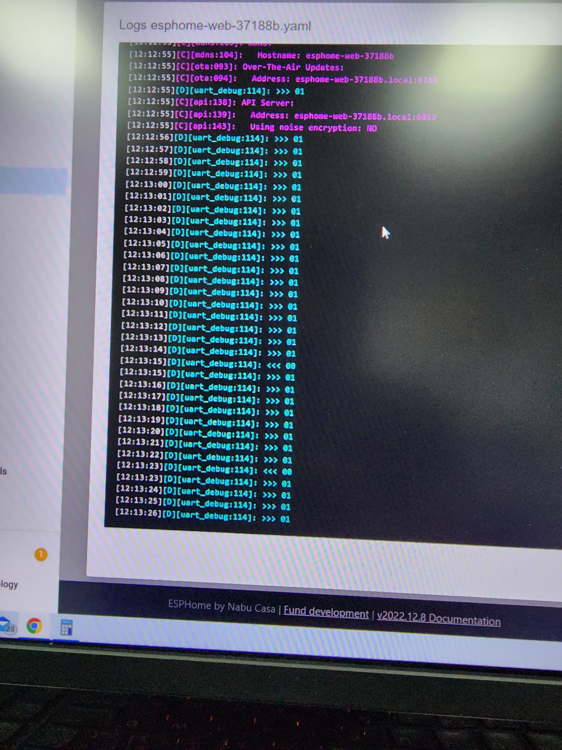
From my sensor:


I get input as 00 in uart debug on RX pin on the board.please help. When I wave my acrossthe sensor it returns 00
How did you connect the wires?
The esp rx links to the sensor tx.
The esp tx links to the sensor rx.
What byte are you sending?
I contacted the manufacturer and they send a debugging software. When I checked with that , the sensor was damaged, so I got another one, but now there are no 00 even. The software is using 0xff and I tried with that but no output in esphome
should I connect to the board’s rx and tx pins or i can declare any pin as rx and tx.