Some of you may be looking for a solution to monitor your home’s water usage both reliably, and above all else, at a low cost. ESPHome is an excellent platform to base this type of project upon due to it’s versitality and cheap chips. In this project, I will be using a Wemos D1 Mini, but you’re welcome to substitute any ESPHome compatible chip that has analog capability.
There are other projects that exist to measure your water meter. If you’re lucky, your meter may already be broadcasting it’s usage data wirelessly. And usually in this case, the data is unencrypted and you can sniff it out of the air yourself using a Software-Defined Radio (SDR). Check out this post by debsahu if you think that method could work for you.
Other people have used a proximity sensor like pictured below to count the revolutions of your meter’s needle gauge. But if you have a meter like mine, that won’t work because the needle gauge is plastic, and therefore undetectable by a prox sensor.

ESP32 even has the capability to run machine-vision software to decode the dials on your meter, and parse them into data that home assistant can understand. But if you’re like me and want a much simpler way to achieve this with (reasonable) accuracy and low cost, please read on!
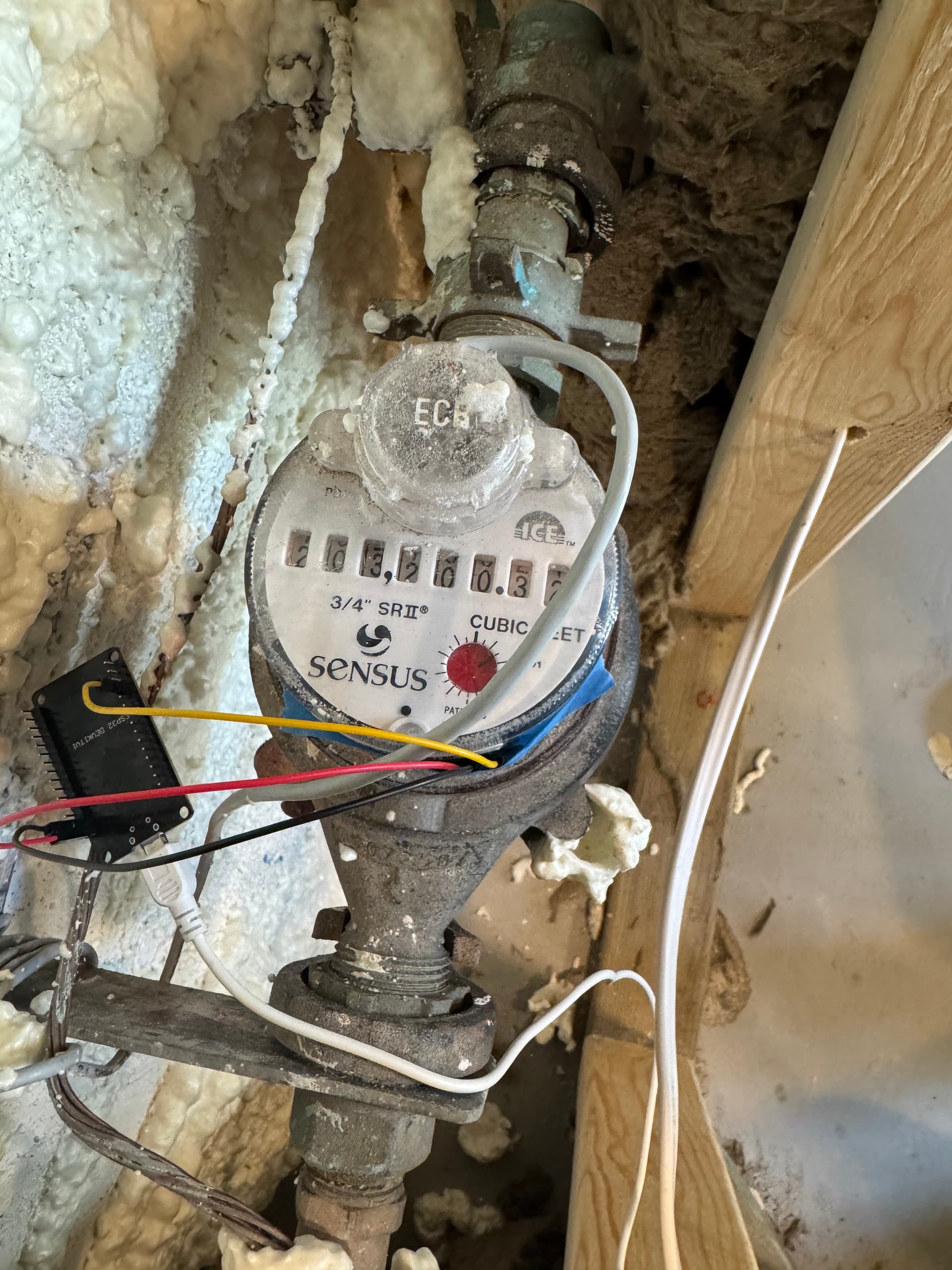
My meter is a Sensus SRII/SR-A with a “dumb” TouchRead module mounted outside. This style of meter requires a person to physically come by to retrieve the usage values. If you live in a more dense neighborhood, chances are you may have a wireless module outside, which looks like the tan-colored box in the photo below. If that’s the case, look above for a link to a way you can wirelessly read your water meter.


The Sensus SRII/SR-A has a rotating disc inside the housing that is (just barely) detectable by a very sensitive hall-effect sensor. In this project, I used a Texas Instruments DRV5056 sensor. It is entirely analog, with a voltage output proportional to the strength and polarity of the magnetic field. This sensor is great because it’s super tiny and sensitive. Making it perfect for squeezing it into even the smallest of spaces, and be able to detect extremely small magnetic fields. Since my meter’s magnetic flux while rotating is incredibly small, I needed the best chance to detect it. As such, this method should work for nearly any water meter using the same technology as the Sensus.

To create this project yourself you’ll need:
- An ESPHome compatible microcontroller.
- A TI DRV5056A1ELPGMQ1
- A soldering iron and mild soldering skills.
- Heat-shrink tubing (quite small).
- Small, stranded wire.
- A sprinkle of ambition.
Firstly, let’s set up the hall effect sensor and get it wired up. According to the DRV5056 datasheet, this hall effect sensor can operate with 3.3 V and 5 V power supplies. The D1 Mini provides both of these voltages, but we will only be using the 3.3 V rail for this project because the D1 mini can only accept up to 3.3 V on it’s analog input. The DRV5056 will output an analog voltage respective to the input VCC voltage. Since we want to cap our maximum output voltage coming from the sensor to no more than 3.3 V, we will simply supply it with that voltage.
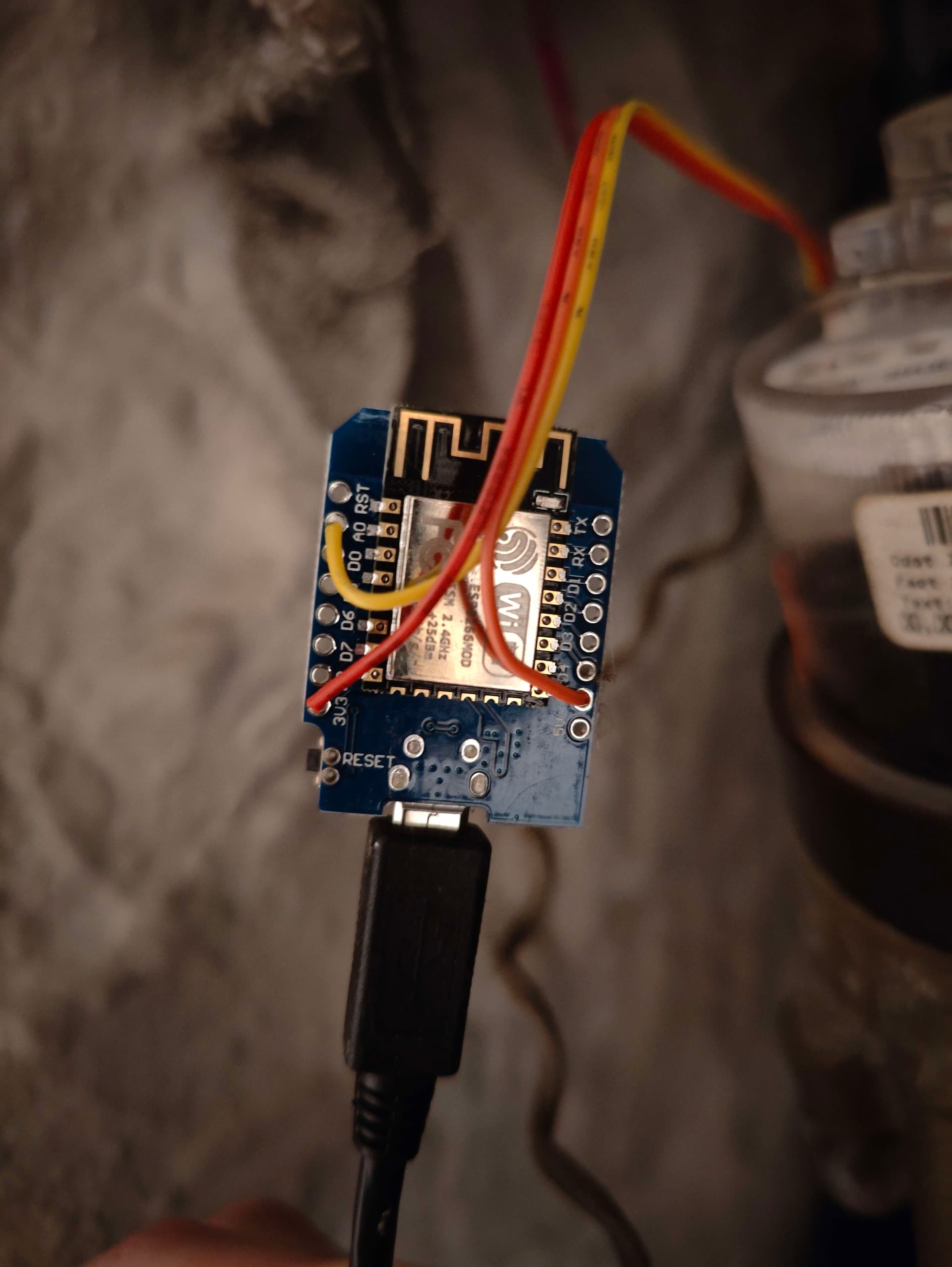
The package’s pins 1,2,and 3 are VCC, GND, and OUT respectively. So we will be connecting our VCC to the 3.3 V pin on our ESP32, the GND to any ground pin, and the OUT to an analog pin.

Prepare some small-diameter shrink tubing and slide it over your wires before soldering. To improve durability of the sensor, I suggest using one more larger piece of shrink tubing that will fit around all wires. Then, you can slide the entire piece over the leads to protect them, and the delicate solder connections.

The Completed Sensor
Image from: https://www.instructables.com/Monitoring-residential-water-usage-by-reading-muni/
After I was done wiring up my sensor, I soldered it’s wires to my D1 mini at the appropriate pins. Yours may differ depending on the ESP32 board you decide to use. But as an example, here is what mine looked like:
Now it’s time for some code!
One downside of using this very sensitive hall-effect sensor is the amount of noise it picks up from the surrounding area. Depending on EMI from nearby appliances, vibrations, or nearby secret government research, you may find the values you receive from the sensor are sometimes quite erratic. I was somewhat unlucky, and my values fluctuate about +/- 10 when the meter is not running. However I only see a change of +/- 12 or so when the meter actually IS running. So in my case, it was very difficult to filter out the noise. Hopefully your meter will fluctuate more when it’s running than mine.
globals:
  id: total_pulses
  type: int
  restore_value: True

sensor:
 # Analog read of the hall effect sensor
  - platform: adc
    pin: A0
    update_interval: 250ms
    raw: true
    id: water_hall_effect

 # Gallons used calculation
  - platform: template
    name: "Gallons of Water Used"
    device_class: water
    unit_of_measurement: gal
    state_class: total_increasing
    accuracy_decimals: 2
    update_interval: 10s
    lambda:
      return id(total_pulses) * 0.11692;

 # Increment a 'pulse' each time value of the hall effect sensor crosses a threshold
binary_sensor:
  - platform: analog_threshold
    name: "water_pulse"
    sensor_id: water_hall_effect
    threshold:
      upper: 197
      lower: 189
    on_press:
      then:
        - lambda: id(total_pulses) += 1;
Breaking down this code from top to bottom:
- Global variable definition. This
total_pulsesvariable is used to track the total number of times 1 revolution is detected by the sensor. Therestore_valueconfig variable is set to true, so that if and when the ESP32 reboots, this value is restored to it’s previous value, and your accumulating total of water used is not lost. - Sensor definitions. The first is an
adctype sensor. The ADC (analog-digital conversion) sensor will acquire the analog signal from the sensor and convert it to a digital value. I set this to update every 250ms so that when water usage is very high (such as when my washing machine is filling), the sensor doesn’t miss a revolution of the disc.raw: trueis set to make it easier to read the value changes as they feed in. Setting the raw variable will bring your values in at the resolution of the ADC, which in my case is a value from 0-1024. This sensor does not need broadcast to home assistant, so I did not give it aname:. Giving a sensor only anid:inherently makes the sensor internal only. - The second sensor is a template sensor that calculates gallons used based upon the pulses coming in. the lambda function at the bottom
return id(total_pulses) * 0.11692;multiplies our global variabletotal_pulsesby a factor I determined over the course of a few days. More on finding this factor for yourself later. This sensor was given
name: "Gallons of water used" # Name reported to home assistant
device_class: water           # Type of device reported to home assistant
unit_of_measurement: gal      # Units for the value, important for the energy dashboard
state_class:                  # Important for appropriate statistics tracking
accuracy_decimals: 2          # Limits number down to 0.00
update_interval: 10s          # Updates home assistant every 10s with new water usage.
- Finally, we have a binary sensor who’s job is just to count the number of pulses and write that value to the global variable. Again, we are using the global variable to keep our values intact in case of ESP reboot. Otherwise our values would be volatile, and the home assistant energy dashboard doesn’t take kindly to having it’s incoming data suddenly changed rapidly. This sensor is an
analog_thresholdsensor, meaning it will trigger any time the upper or lower threshold is crossed. 197 and 189 are the values I found work best for my situation. You will have to use trial and error to find the best values for your case. I did give this sensor a name though, that way it is reported to home assistant and I can use this to derive my multiplication factor. Theon_pressfunction runs when the threshold sensor changes from ‘False’ to ‘True’ and not the other way around. This way we know that each time the lambda filter runs, we have received 1 pulse. For example, if we instead usedon_state, the filter would pass double the amount of times it would otherwise. So our multiplication factor would need to be halved.
Once your code is uploaded, you will need to find the best placement for your hall effect sensor. With the DRV5056, the top side (shown in the photo above) is the side which is most sensitive to magnetic flux. I found it’s easiest to open the logs to your ESP32 module and watch the data come in. You will see the value of your water_hall_effect sensor change every 250ms, which should give you a good indication of how close you are to the disc inside your water meter.
I found on mine, the best position to place my sensor was the 11 o’ clock position on my meter. There, I found my highest value was 199, and my minimum was 186 (which is very narrow!). I didn’t want to set my thresholds to these values however, instead I set them slightly off of these values so that my sensor would consistently trigger when the water was running, and trigger minimally while the meter was idle.

Note: My sensor still produces false positives occasionally, but by taking a multi-day average, I am able to filter out these minor triggers and still get a decently accurate reading over the course of a week or so. Another Note: I could probably get even more accurate values by taking a rolling average, but I wanted this to be as simple as possible. I am still happy with the readings I get using this method.
I hope this guide helps! If you made your own, comment below! Or if you have ideas on how to improve this design, also leave a comment!