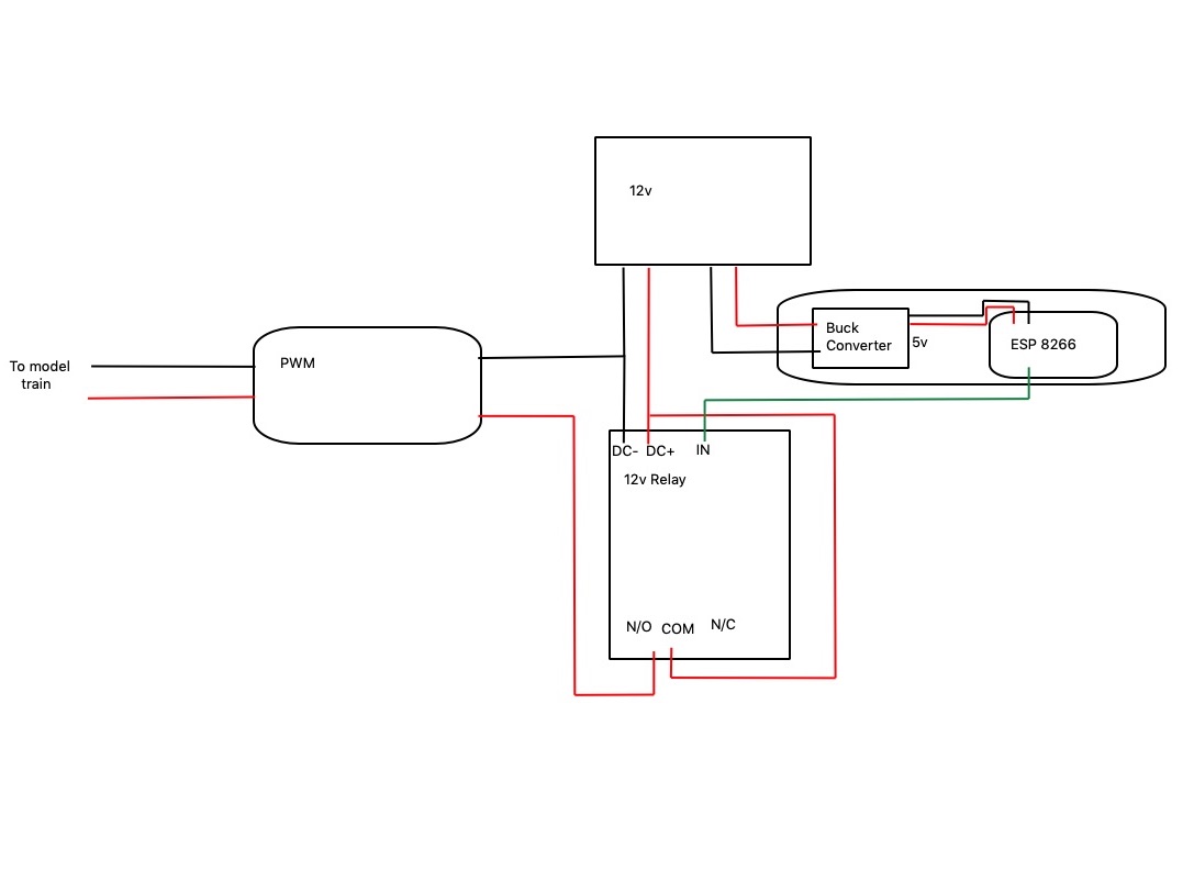
I’m looking to control a model train (12v) with esphome via a simple relay (GPIO switch).
The power supply that I have available is 12v. My understanding is that I could step this down to 5v to power the ESP and then use a GPIO to go into my 12v relay(IN).
Please let me know if this diagram looks correct. I’m uncertain as to whether a common ground is required between the 12v supply on the relay and the ESP in order for the trigger(GPIO) to work.
Voltage converters have GND in common on the input (12V) and output side (5V). The exception is converters that are galvanically isolated.
I don’t suppose you use one.
Are you sure your relay has a DC+, DC- and IN? A normal relay only has two connections to the relay coil which do not require a special polarity.
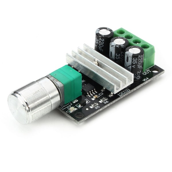
I am also a bit puzzles by the “PWM” in your left side box. Pulse Width Modulation normally uses frequencies in the kHz range. Nothing you could do with a relay.
Thanks @pepe59 , I didn’t think of that , there is only 1 12v supply so it is coming from the same ground. @Jpsy with the PWM I’m merely cutting(and linking) the live wire from my 12v supply that powers the unit.
Here are some pics of the components. I’ll give it a try in the morning and see how it goes.
I would normally use a 5v relay(which would make life easier) but the 5v relays I have are a bit bulky for this project. I’m making a rotating christmas village , the bottom tier is where the train goes.
If the board is indeed powered by 12V, I have a similar relay and the signal (in) requires 12v to activate. The 3.3v out from the nodemcu is not enough to trigger it.
Ahhh, I see. I was not aware of these relays with optocouplers and active electronics on the input side. @Mikefila it looks like these boards come in different versions for many DC voltages. 12 V with a trigger of 3,3/5 V is one of the available options.
Connected everything as per diagram, works flawlessly. The relay has a “High”(0.5-1.5v) and a “Low”(3-5v) trigger. I have the jumper connected on “High”.