Using an ESP8266 Dual Relay Combo Board with Home Assistant

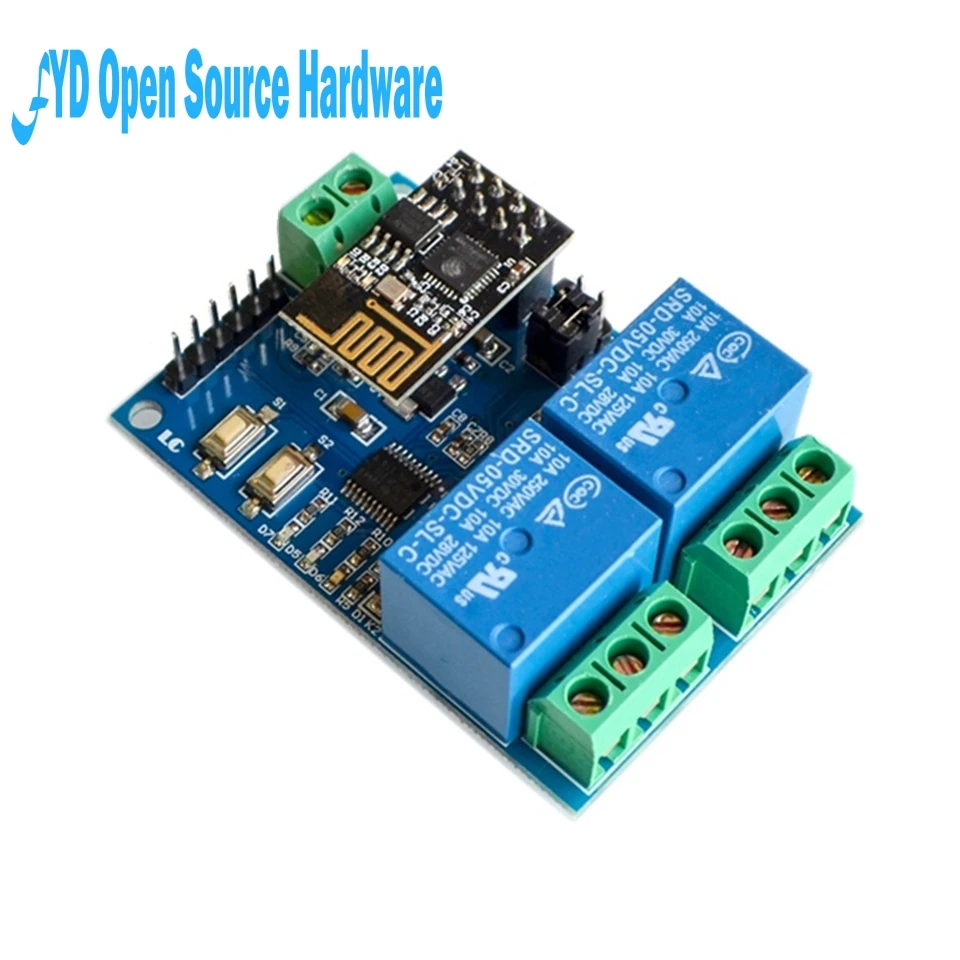
Hello everyone! I currently need 2 relays that I want to be able to control using home assistant and has physical switches to toggle on/off, and I found this combo board on AliExpress that hardware-wise looks like it has everything I need: 2 relays, wifi, and a physical switch. Has anyone ever got these wifi-relay combo boards to work with home assistant? I saw a video on YouTube showing that you could control this board straight out of the box using an Android App called ESP2Relay. Would I be able to use it straight out of the box or would I have to flash it with ESP Home/Tasmota? Thanks for your time guys!

Hereā€™s the product:
https://www.aliexpress.com/item/32963636755.html

Hereā€™s a video I found about setting up this board using it with ESP2Relay:

And hereā€™s what the seller had to say about the item:
1.Onboard ESP-01 WiFi modules and high performance microprocessor STM8S103.
2.The module has 2 operating modes of work:
Mode 1: mobile phone is directly mounted on WiFi module.
Mode 2: mobile phones and WiFi modules are equipped on routers simultaneously
Additional function: it can also be used as USB relay when ESP-01 is pulled out.
3.Transmission distance: In an open environment, the maximum stable transmission distance is 100M when the mobile phone is mounted on the WiFi module.
4.When the WiFi module and mobile phone are carried on the router at the same time, the transmission distance depends on the signal strength of the router.
5.Onboard 5V, 10A//250V AC 10A//30V DC relay, which can be continuously pulled for 100 thousand times, has diode discharge protection, short response time.
6.The use of Smartcongig technology in the mobile phone on the APP ESP-01 WiFi module to complete the account and password configuration, configured username and password memory function.
7.Board mode selection and real time working status indicator.
8.Reserved UART debug interface and STM8 SWIM program download interface.

You will need to flash it if you want to control it from HA.

That is kind of an interesting one there; looks like an stm8 board with 2 relays, and an esp-01 strapped on top for wireless input. Itā€™s price is hard to argue. :smiley: ESPhome supports the esp-01. So you would just need to determine what outputs are needed to turn the relays on/off. The esp-01 has pretty much just 2 gpio pins available, gpio0 and gpio2 (also has tx, rx, and ch-pd, but those typically arenā€™t used for io). It would be a good guess that those 2 pins operate the relays.

Now, how do you flash the esp-01 with esphome to even try this?

  1. Use an ftdi adapter, and flash esphome directly to the esp-01 device.

  2. The product info seems to suggest something that like ā€˜smartcongig technology and configuration some configured items, with reserved uart debug and swim download interfaceā€™. :crazy_face: Maybe a quick call to the vendor or manufacturer will clear things up about how you might flash the esp-01 through the stm-8 usb interface. You would at least need to wire up a usb cable to that board; doesnā€™t look like thereā€™s a usb port soldered on there.

After esphome is flashed, if configured for it, you can upload future firmware updates OTA.

I have one running ESP home, hereā€™s my config. I basically use it to ā€œpressā€ the Power and Reset buttons on a PC.

I removed the ESP-01 and programmed it directly using an FTDI adapter. Once done and the ESP-01 board is re-connected to the relay board, you can do OTA edits/updates

Donā€™t think there is anywhere to connect a physical switch though, although Frenckā€™s doorbell has a hack to let you have one input:

esphome:
  name: pc_remote
  platform: ESP8266
  board: esp01_1m

wifi:
  ssid: "xxxxxxxxxxxxxxxxx"
  password: !secret wifi_password
  manual_ip:
    static_ip: '192.168.1.215'
    gateway: '192.168.1.1'
    subnet: '255.255.255.0'
  ap:
    ssid: "ESP_pc_remote"
    password: !secret wifi_password

captive_portal:
logger:
  baud_rate: 0
api:
ota:

uart:
  baud_rate: 115200
  tx_pin: GPIO1
  rx_pin: GPIO3

binary_sensor:
  - platform: status
    name: "PC Remote ESP Status"

switch:
  - platform: template
    id: relay1
    turn_on_action:
      - uart.write: [0xA0, 0x01, 0x01, 0xA2]
    turn_off_action:
      - uart.write: [0xA0, 0x01, 0x00, 0xA1]
    internal: yes

  - platform: template
    id: relay2
    turn_on_action:
      - uart.write: [0xA0, 0x02, 0x01, 0xA3]
    turn_off_action:
      - uart.write: [0xA0, 0x02, 0x00, 0xA2]
    internal: yes

  - platform: template
    name: "PC Remote Power"
    id: pcpower
    turn_on_action:
    - switch.turn_on: relay1
    - delay: 500ms
    - switch.turn_off: relay1
    - delay: 500ms
    - switch.turn_off: pcpower

  - platform: template
    name: "PC Remote Reset"
    id: pcreset
    turn_on_action:
    - switch.turn_on: relay2
    - delay: 500ms
    - switch.turn_off: relay2
    - delay: 500ms
    - switch.turn_off: pcreset
5 Likes

Hello Rendylrawan, Holdestmade

I am also very interested by your posts.
I amgoing to work on this during this next week-end.

Holdestmade, thank you very much for your information :blush: but I am now wondering
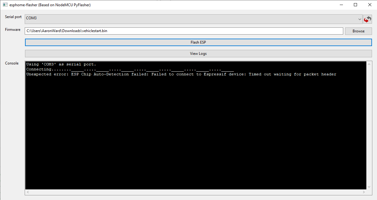
  1. have you used espflasher on PC, or have you used ESPHome add-on from HA, so as to flash the ESP?
  2. have you consider the ESP-01 generic as firmware to flash?
  3. maybe, we can find a didactical video tuto of this process on the web? Or maybe you have a relevant one :sweat_smile::wink:

I thank you in advance for your answer.

Initially, I download the binary from esphome and flash to the ESP-01 the first time with ESPHomeFlasher, then use OTA for any changes

Not sure what you mean

In fact, the add-on Esphome in HA proposes different binaries to flash. I understand that the binary selected generated seems to be sent to a PC, which flashes via esphome flasher on the esp with the help of an ftdi plugged on the pc.
On the screenshot enclosed, you see that the esphome add-on proposes different binary/firmwares and I wanted to know which one we have to choose? The ā€œgeneric ESP8266ā€?

It doesnā€™t matter as you overwrite it with the code above, but I think you select Espressif ESP-01 512k module and change it from ESP01 to ESP01_1m


esphome:
  name: pc_remote
  platform: ESP8266
  board: esp01_1m

Hello, I have started to configure using your code.yaml (except for the lines static_ip, gateway and subnet that I donā€™t put yet what are the information to give here?).
When I validate it is ok, but when I compile it blocks and freeze the pi (see picture bellow).
I donā€™t understand how to solve this issue :sob: do you think it is because I havenā€™t put the line static_ip, gateway, subnet ?
If needed :frowning:

  • does static_ip is the ip of the raspberry-pi?
  • does the gateway the ip of my router?
  • subnet is usually 255.255.255.0 isnā€™t it?

I am wondering if it would be because I have Home Assistant container? :thinking:

Thank you so much for your helpšŸ™

, I donā€™t know how to progress :cry:

I have found the solution, by stopping other HA modules while compiling because it requires 500Mo of RAM
:+1:

Thatā€™s awesome! I canā€™t wait to try it myself!

Thanks everyone for the replies!

Yes, on a pi3b w/ little RAM you will often run in to these kind of problems when compiling esphome firmware. You found a workaround that may well work for your case. If not, you can also upgrade to a pi4 which has the RAM to handle compiling without issues even with lots of things running in the background. Alternatively (I havenā€™t tried this myself), the devs say itā€™s not hard to compile esphome for a first flash using arduino, pio, or similar standard IDE on a desktop/laptop that has enough resources.

1 Like

I got a 2-channel relay with STM8S103, and Iā€™ve tried to turn it on with both baud rate 9600 and 115200. Not sure what to do, anyone know why itā€™s not working?
Hereā€™s my config:

uart:
  baud_rate: 9200
  tx_pin: GPIO1
  rx_pin: GPIO3

switch:
  - platform: template
    name: 'Relay 1'
    id: relay1
    turn_on_action:
      - uart.write: [0xA0, 0x01, 0x01, 0xA2]
    turn_off_action:
      - uart.write: [0xA0, 0x01, 0x00, 0xA1]
    optimistic: true
  - platform: template
    name: 'Relay 2'
    id: relay2
    turn_on_action:
      - uart.write: [0xA0, 0x02, 0x01, 0xA3]
    turn_off_action:
      - uart.write: [0xA0, 0x02, 0x00, 0xA2]
    optimistic: true

I had a similar issue with an identical looking board to the op, but it seemed to be using a Nuvotron chip.

To make it work with esphome some preamble had to be added to the commands:

  - platform: template
    id: relay1
    turn_on_action:
      - uart.write: [0x0D, 0x0A, 0x2B, 0x49, 0x50, 0x44, 0x2C, 0x30, 0x2C, 0x34, 0x3A, 0xA0, 0x01, 0x01, 0xA2]
    turn_off_action:
      - uart.write: [0x0D, 0x0A, 0x2B, 0x49, 0x50, 0x44, 0x2C, 0x30, 0x2C, 0x34, 0x3A, 0xA0, 0x01, 0x00, 0xA1]

  - platform: template
    id: relay2
    turn_on_action:
      - uart.write: [0x0D, 0x0A, 0x2B, 0x49, 0x50, 0x44, 0x2C, 0x30, 0x2C, 0x34, 0x3A, 0xA0, 0x02, 0x01, 0xA3]
    turn_off_action:
      - uart.write: [0x0D, 0x0A, 0x2B, 0x49, 0x50, 0x44, 0x2C, 0x30, 0x2C, 0x34, 0x3A, 0xA0, 0x02, 0x00, 0xA2]

It now works fine (115200 baud) but make sure the board isnā€™t in mode 2 - mine wouldnā€™t respond to the ESP commands in that mode, I had to set it back to mode 1 by holding SW1 while power was applied (the board LED should change from blue to red).

3 Likes

Do you have a link for where to purchase one of these relay board combos?

I got mine from Amazon, seems to be the same relay board just a slightly different chip - but as above works just fine with the extra preamble added.

1 Like

Need some assistance from you all on flashing this device. I have a FTDI adapter and I have connected it to the appropriate pins on the ESP device. When using esphome-flasher on Windows 10 (running the app in elevated mode) I get the following error:

And of course the ESPHome code that was compiled and downloaded to upload to the ESP. I did try both ESP01 and ESP01_1m like above. No luck. Thoughts??

esphome:
  name: vehicles
  platform: ESP8266
  board: esp01

wifi:
  ssid: "SSID"
  password: "YOUWOULDLIKETOKNOW"

  # Enable fallback hotspot (captive portal) in case wifi connection fails
  ap:
    ssid: "Vehicles Fallback Hotspot"
    password: "something here"

captive_portal:

# Enable logging
logger:

# Enable Home Assistant API
api:

ota:

After reading the doorbell instructions AND dual wiring up the ESP32 now I get this error:

Got it working! Appears to be a bad ESP32 module.

Thanks a ton man, i was giving up on this board already, but you saved the day.

1 Like