I’ve just finished the final touches on my 100% off-grid PV installation and HA Energy Dashboard integration and just wanted to share this with the community as I’ve seen some interest on my other Victron integration thread and have noticed some questions in the forum around power vs. energy vs. utility meters and how to configure all these to integrate with the Energy Dashboard.
This is quite a long post as there is a lot to describe but I’ve tried to break it down into key sections and will publish it into 2 or 3 posts to make it more digestible.
My purpose here is to a) give back a small part of what I got from this great community and b) document what I believe is an interesting real-life case which fits right into the HA philosophy; automate as much as you can.
TLDR
100% off-grid 16kW PV installation using Victron/Fronius/Pylontech gear with KOHLER with gas backup generator exposing all system data to local network via modbus and MQTT broker ingested by hassos instance running on dedicated ESXi VM.
Main HA integrations used are modbus, MQTT, integration, derivative, utility meter, Fronius, Forecast.solar, Solcast and ESIOS API.
Lovelace UI uses custom Multiple Entity Row, Tesla style solar power card (for power flows) and Energy Dashboard (for energy accounting).
Extensive use of HA automations to independently manage loads such as irrigation system, house water pumps, and swimming pool as well as generator start/stop using extrapolation of battery discharge time (HA derivative integration) combined with next-hours and next-day solar production forecast (Solcast and Forecast.solar).
Using real-time energy cost (Spain ESIOS API - the installation is in Alicante region) we calculate the equivalent energy cost should the house be grid connected to feed the ROI - Return On Investment economic model.
Screenshot of energy dashboard on a cloudy day with generator feed-in (the grid is the generator, we are 100% off-grid; I haven’t changed the icon)

The long read
1. Intro and context
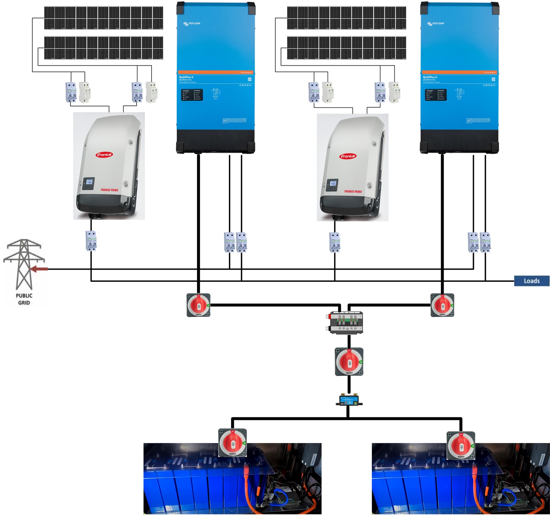
The house is 100% off-grid for energy, water and waste. Electricity is produced by a combination of Victron/Fronius/Pylontech gear with a SDMO/Kohler gas backup generator. I have 40 x 405Watt panels on the flat roof, facing due south, at a 35 degree angle, for a total maximum theoretical PV output of 16.2kW. On good days, I have seen readings of 15.8kW. These are connected in 2x2 strings of 10 panels each to a couple of Fronius Primo 8.2 solar inverters which are in turn connected to the house 230VAC single phase grid provided by the master Victron Multiplus II 48/5000 inverter/charger which drives another 2 Multiplus II 48/5000 for a total capacity of 15kW. The 3 inverters/chargers are connected to a bank of 12 Pylontech US3000C 48V Lithium batteries for a total capacity of 42kWh of storage energy. Finally, this set-up is complemented by a gas back-up generator SDMO/Kohler RESA14 11kW power which I throttle to about 80% to work on the specific gas consumption sweet spot (max electrical energy per gas consumption). The choice of multiple inverters and battery banks is deliberate to ensure resilience in case of failure of one component.
The installation is connected/monitored to/by a Victron CCGX device which exposes all the system data to the local network via modbus TCP and its inbuilt MQTT broker. The reason why both integrations are used is described later in detail.
Simplified schematic of installation

Sizing of the components, especially the battery capacity, is based on a winter daily energy consumption of ±30kWh and a summer consumption of ±60kWh the increase being the 3HP swimming pool filtration and jacuzzi electric motors. Based on historical data, battery capacity is designed to ensure generator turns on during winter season to provide up to 2% total yearly energy needs for a 98% solar coverage. We want the generator to work from time to time to ensure it is well exercised and fully operational.
2. Requirements and system architecture
Being totally isolated we produce our own electricity, water (from our own water well) and manage our waste while complying with all local regulations (specifically in terms of waste management). These are some of the key requirements for this build:
- No compromise on confort such as e.g. reduce electrical consumption on grey days → back-up generator
This is our main residence and we don’t want to skip on life’s conforts. We are off-grid so once the investment is made there is no point in saving PV electrical energy. Since we opted for 100% electricity there was no way we could guarantee full supply no matter how big the battery storage capacity. The generator is a modest investment compared to batteries and is designed to run for about 100 hours maximum per year consuming roughly 300kg of propane. This means the house is not 100% “green” but neither are lithium batteries and we are sure we have backup energy no matter what. - No internet dependency → 100% local data feeding the critical automations
This one is self-explanatory. - Delegation of logic to lowest level possible → Victron controller for energy, KNX for everything else
In last resort, I don’t want to rely on a server to keep water tank full or to start the generator. For critical stuff we have 2 or 3 cascading levels of logic/automation so if the server running HA goes bust we are covered. - Use of standards and vendor agnostic → Home Assistant, MQTT, modbus, etc.
The standards part is important as I found myself down a rabbit hole more than once. When I mean standards, I include for instance running HA as hassos and not spinning up my own containers and the whole 9 yards. I know hassos is more limited than running my own containers but as much as I like to play around I want this to be as reliable and as uncomplicated as possible. One thing is development, another is production. I rely on this for production.
Vendor tie-in is not good, limits your choices and puts you at the mercy of their plans, or lack of. This is the part where I praise the HA team for the wonderful, exceptional work they’re doing. I started out with HA 5 years ago and boy, has it come a long way. THANK YOU.
The following image is a simple architectural view of the set-up. Layer 1 implements basic logic mostly at the level of the KNX sensors/actuators (e.g. hot water production is exclusively driven by hot water tank temperature and that simple sensor can control the full process. Shading control is managed at the level of each blind, etc.).
Layer 2 represents mostly the transport layers and/or protocols used. I try to stay as close to the native capabilities of the devices and reduce interfaces.
Layer 3 implements more complex logic. KNX logic modules allow for instance calculating the average temperature in the house which in turn drives HVAC. DALI is the standard for all the lights and manages group behaviour such as dimming, colour, etc. VenusOS is the open Victron OS and manages the whole PV installation via parametrisation.
Finally level 4 implements even more complex logic with the key difference that it is not mission critical. Not to disparage HA as a tool, on the contrary, but as it must run on a computer it is more prone to failure than the lower levels. For instance calculating battery discharge rate using HA derivative I can extrapolate if it will need charging by the generator during the night so I can anticipate turning it on a couple of hours in the evening so it doesn’t disturb sleep hours. This is convenient, but not critical. If it fails, the inverter/charger at the lowest level kicks-in to turn the generator on.

3. MQTT integration
To control the PV installation I use the Victron CCGX unit but this applies to all Victron control units including the latest Cerbo. I will from now on call these the GX device as they all run Victron’s VenusOS which is openly available at GitHub - victronenergy/venus: Victron Energy Unix/Linux OS
At one point, just for fun, I built my own device using a RPI3 with canbus header for the batteries and it worked perfectly fine. The CCGX gives me the added value of an inbuilt screen with can be convenient during set-up.
Victron’s GX devices include an in-built MQTT broker which can be activated in Menu/Settings/Services. This sets it up as a MQTT broker and sends all your installation data as MQTT message topics on the network. As mentioned above, it is possible to collect this [almost] same information using modbus over TCP with [almost] exactly the same results. MQTT is rather user-friendly in my view as using MQQT Explorer you can navigate the literally hundreds of topics available.

Note: I use Plaintext which does not require user or password and is over port 1883, but to activate it you also need to activate SSL. Using Plaintext your MQTT messages will be open to anyone on your network to read which could be considered a security risk. My take is that if anyone, a potential hacker made it that far, i.e. into your network, he/she could just as well access your GX device directly and do whatever he/she can and not go to the trouble of intercepting MQTT messages.
4. Create a keepalive automation in HA
The GX device MQTT broker needs a keepalive message every 30 or so seconds otherwise it goes to sleep. This is to ensure it doesn’t waste resources when nobody is listening. You need to have your HA send that keepalive message.
The brute force way is to send the basic keep alive message
R/<portal ID>/system/0/Serial
which makes the broker publish everything. A simple way is to create an automation such as the one below (the 12 digit hex characters topic identifier is the MAC address of your GX device which you can find in the Settings menu or in the VRM Portal if you are using it):
alias: mqtt keep alive pour casa - utilise de CCGX
description: ''
trigger:
  - platform: time_pattern
    seconds: /30
condition: []
action:
  - data:
      topic: R/04a316c4f970/system/0/Serial
    service: mqtt.publish
mode: single
From VenusOS version 2.80 Victron does not recommend doing this as there are literally hundreds of messages and you’re only going to need a couple dozen max. Nevertheless, when you are fine-tuning your system you may want to do this because that’s the convenient way to look at all the data the broker publishes while you’re making your choice. Once you figure out exactly what you need you can move to the /keepalive method described in the docs. Again I use an automation to implement it listing on the payload only the topics I use:
alias: CCGX keepalive
description: ''
trigger:
  - platform: time_pattern
    seconds: /30
condition: []
action:
  - service: mqtt.publish
    data:
      topic: R/04a316c4f970/keepalive
      payload: >-
        ["system/0/Ac/ConsumptionOnOutput/L1/Power","vebus/257/Ac/ActiveIn/L1/P","vebus/257/Dc/0/Power","system/0/Ac/PvOnOutput/L1/Power","battery/512/Soc","vebus/257/Ac/Out/L1/F","vebus/257/Ac/ActiveIn/L1/F","vebus/257/Ac/ActiveIn/Connected","battery/512/Soh","battery/512/Dc/0/Temperature"]
mode: single
This limits the chat on the line and if later I need another topic I just need to add it to the list.
5. HA MQTT integration
To integrate the GX MQTT broker into HA and consume the message topics there are basically 2 ways depending on whether you need to set-up your own MQTT broker (for instance if you use other MQTT dependent integrations), or not.
HA MQTT integration implements mosquitto_pub and mosquito_sub so you don’t need to set-up your own broker if this is your only use-case for MQTT. You just need to install HA MQTT integration and configure it to point to the IP address or your GX device (in my case 192.168.1.25) on port 1883.

If you are using your own MQTT broker, I assume here you have chosen the community add-on. If you have yet another set-up most of what follows applies equally but of course location of configuration files will be different depending on your specific installation.
Install MQTT community add-on and configure as follows:
certfile: fullchain.pem
customize:
  active: true
  folder: mosquitto
keyfile: privkey.pem
logins: []
require_certificate: false
Create a file named accesscontrollist in share/mosquitto (use the File Browser add-on, the SMB add-on or whatever you prefer) with the following line
topic readwrite #
This ensures all users can read/write on all topics. If you want to be more restrictive, there are a couple of good threads on the forum you can refer to.
Create another file in share/mosquitto named acl.conf with the following line
acl_file /share/mosquitto/accesscontrollist
This tells your MQTT broker where the access control information is.
Because you now have 2 MQTT brokers, your own and the GX one, you need to bridge them so your HA can collect the message topics published by the GX broker while connected to your own broker. Bridging means simply that your MQTT broker will act as a bridge for the GX broker, passing on the message topics you configure.
To achieve this, create file mosquitto.conf in directory share/mosquitto with the following lines:
connection casa
address 192.168.1.25:1883
topic N/04a316c4f970/# in
topic R/04a316c4f970/# out
topic W/04a316c4f970/# out
The connection statement is just the name of your choice for the broker you want to bridge. Any name will do.
The address is the IP of your GX broker and port 1883.
The topic part defines what you want to bridge in and out in plain receive mode (N), read request using mosquitto_sub (R) and write request using mosquitto_pub (W). I prefer to bridge everything because I’m already throttling the GX device by the /keepalive statement to only the topics I want.
Start the MQTT add-on and look at the logs to check everything is working as expected.
6. Topic discovery
As I mentioned, there are literally hundreds of topics published by the GX device so I use MQTT Explorer to navigate through these and select those which interest me. (here I’m connecting to the HA broker which is the same as connecting directly to the GX device as we have a bridge set-up).

Connect to your MQTT server using its IP. As we allow anonymous login we don’t need username or password. Navigate through the topics and select what you want.

When I first set-up this integration I collected just about every topic I could think of and ended up with a cluttered UI with information overload. As I pruned the topics focusing on the things I was really interested in I went for battery status and power flows and left aside the myriad voltage and current measures available in the system. As my installation is off-grid, the inverter/charger (Victron Multiplus II) uses the mini grid frequency to communicate to the PV inverters (Fronius) so I also have this topic at hand. I was also looking to automate the set-up as much as possible so looked for topics required to power the automations. In the end, I use about a dozen.
7. Power flows and energy accounting
Before moving on to the next steps I’d like to make a short diversion on the theme of power and energy. Apologies if what follows comes across as too simple or simplistic but as I read through some of the forums I noticed there is some potential confusion about power and energy and when you throw in HA’s utility meter integration and the Energy Dashboard its can get confusing.
Energy expresses the capacity to do work and is measured in Joule (SI system - other units are calories, and BTU in Imperial system). A Joule is the energy required to move a mass of one kg by 1 meter. In the context of electricity the unit commonly used is Wh (watthour) or kWh (kilowatthour). Electrical utility meters account for energy and measure kWh. Your electricity provider charges you in kWh.
Power is the rate at which work is done or energy is used/spent. The energy unit, Joule, doesn’t say how fast that mass of 1 kg is moved. If you move it fast i.e. at a fast rate, you need more power than if you move it slowly i.e. low rate. Hence power is energy/time. In the SI system the unit of power is W from James Watt. Solar panels are rated in Watt, inverters are rated in kW (or KVA in the alternative current world - not in scope here), electrical consumers such as fridges, bulbs, motors, etc. are rated in W. A 10W light bulb on for 10 hours = a 100W light bulb on for 1 hour. Both consume the same energy, cost the same money.
The following image represents the power flows in my installation. Solar panels feed the house and/or the batteries and are complemented as backup by the generator (here stopped). These are instantaneous flows (depending on the refresh rate of the system - more on that later) and are all in power - Watts. This was implemented using the excellent Tesla style power card GitHub - reptilex/tesla-style-solar-power-card: Home assistant power card mimicking the one tesla provides for the powerwall app. (I changed the grid icon to represent a generator).

The next image is taken from the HA Energy Dashboard and represents energy balances or accounting; it is updated on a daily basis so we are talking here about daily energy accounting. It tells me that today until now I consumed 28.7kWh of energy, more than 50% (the orange part) directly from the solar panels, the rest (green part) from the batteries. The batteries in turn were charged to 100% by the solar panels. HA updates the Energy Dashboard hourly and resets it to zero at midnight (but keeps history - more on that later).

8. Set-up of the power flows
The power flows diagram tells us what we need to measure; how much the solar panels or the generator produce, the house consumption, and the battery power which can be positive (charging) or negative (discharging). Looking through the Fronius integration and the GX device MQTT topics these are what we need:
-
From Fronius integration:
sensor.power_ac_fronius_inverter_1 and _2 (I have 2 inverters) - PV production (this data is also available as a MQTT topic but I prefer to get it at the source) -
From MQTT topics
N/04a316c4f970/system/0/Ac/ConsumptionOnOutput - the house consumption
N/04a316c4f970/vebus/257/Ac/ActiveIn/L1/P - the generator (or the grid if I was connected to the grid)
N/04a316c4f970/vebus/257/Dc/0/Power - the power into/from the battery
These sensors are set-up in my sensor.yaml file. Depending on your installation your topics will differ but the flows will be similar.
These are raw flows and I need to calculate what power goes where. For instance, during the day and when the battery state of charge is <100%, the solar panel production goes partly to the house, partly to charge the batteries. It gets more complicated if the generator is also on, 2 inputs and 2 outputs. The Tesla card requires at minimum 5 entities, none of which is made readily available by the PV system:
        grid_to_house_entity: sensor.grid_to_house
        grid_to_battery_entity: sensor.grid_to_battery
        generation_to_battery_entity: sensor.generation_to_battery
        generation_to_house_entity: sensor.generation_to_house
        battery_to_house_entity: sensor.battery_to_house
For the sake of readability, I used the Tesla card terminology where
grid = generator
and
generation = solar panels
Here is the logic used to derive each value form the available dataset:
grid_to_house:
If the generator is on and the solar panels are producing, the system prioritises the panels to feed the house consumption. If the generator is ON, AND solar production > house consumption THEN grid_to_house = 0 (all power from generator goes to the batteries).
Otherwise, the generator contributes the missing part to the house consumption, the rest goes to the batteries. Trivial if the generator is OFF, then 0.
- sensor:
  - name: Grid to House
    unique_id: grid_to_house
    state_class: measurement
    device_class: power
    unit_of_measurement: 'W'
    state:  >
      {% if is_state('sensor.etat_generateur', '1') %}
        {% if ( states('sensor.pv_on_output') | float(0) ) > ( states('sensor.consumption_on_output') | float(0) ) %}
          0
        {% else %}
          {{ ( states('sensor.consumption_on_output') | float(0) ) - ( states('sensor.pv_on_output') | float(0) ) }}
        {% endif %}
      {% else %}
        0
      {% endif %}
grid_to_battery
This is more or less the reverse logic. If the generator is ON, AND the solar production > house consumption, THEN all the generator production goes to charge the batteries.Otherwise, it is the rest of the total production (generator + solar panels) - what is consumed by the house.
- sensor:
  - name: Grid to Battery
    unique_id: grid_to_battery
    state_class: measurement
    device_class: power
    unit_of_measurement: 'W'
    state:  >
      {% if is_state('sensor.etat_generateur', '1') %}
        {% if ( states('sensor.pv_on_output') | float(0) ) > ( states('sensor.consumption_on_output') | float(0) ) %}
          {{ states('sensor.active_in_power') | float }}
        {% else %}
          {{ ( states('sensor.active_in_power') | float(0) ) + ( states('sensor.pv_on_output') | float(0) ) - ( states('sensor.consumption_on_output') | float(0) )}}
        {% endif %}
      {% else %}
        0
      {% endif %}
generation_to_house:
We saw above that when solar and generator are producing the system prioritises the flow of power from the panels to the house. So if solar panel production > house consumption THEN what goes to the house from the solar panels = the total solar production - what is going into the battery (which is charging because solar power > house consumption) + what is going from the generator to the battery. This last term is important because if solar and generator are both producing then they can both charge the battery.
- sensor:
  - name: Generation to House
    unique_id: generation_to_house
    state_class: measurement
    device_class: power
    unit_of_measurement: 'W'
    state:  >
      {% if states('sensor.pv_on_output') | float(0) > states('sensor.consumption_on_output') | float(0) %}
        {{ states('sensor.pv_on_output') | float(0) - states('sensor.battery_power') | float(0) + states('sensor.grid_to_battery') | float(0) }}
      {% else %}
        {{ states('sensor.pv_on_output') | float(0) }}
      {% endif %}
generation_to_battery:
Here we can use entities calculated above. What goes to the battery is equal to the total solar production - what goes to the house. Nothing is gained, nothing is lost. And if there is no solar power both are zero so the difference is zero too.
- sensor:
  - name: Generation to Battery
    unique_id: generation_to_battery
    state_class: measurement
    device_class: power
    unit_of_measurement: 'W'
    state: "{{ states('sensor.pv_on_output') | float(0) - states('sensor.generation_to_house') | float(0) }}"
battery_to_house:
The last term needs to take into account the sign of the power flow into/from the battery. If positive, it is charging so no flow from battery to the house. If it is negative, all the flow is to the house as there are no other consumers. The Tesla card only accepts positive flows hence the change of sign.
- sensor:
  - name:  Battery to House
    unique_id: battery_to_house
    state_class: measurement
    device_class: power
    unit_of_measurement: 'W'
    state:  >
      {% if states('sensor.battery_power') | float(0) < 0 %}
        {{ states('sensor.battery_power') | float(0)*-1 }}
      {% else %}
        0
      {% endif %}
These are all power flows expressed in Watts and lead to the complete power flow diagram expressed in the Tesla card. I customised the grid icon, prefer to show Watts instead of kW, and added a couple of sensors to the bubble entities. For full details check-out the GitHub site. This card can be added with HACS.
      - type: custom:tesla-style-solar-power-card
        name: lapa
        show_w_not_kw: 1
        grid_icon: mdi:engine
        grid_to_house_entity: sensor.grid_to_house
        grid_to_battery_entity: sensor.grid_to_battery
        generation_to_battery_entity: sensor.generation_to_battery
        generation_to_house_entity: sensor.generation_to_house
        battery_to_house_entity: sensor.battery_to_house
        battery_extra_entity: sensor.battery_soc
        house_extra_entity: sensor.ac_out_frequency
        generation_extra_entity: sensor.solcast_forecast_today_remaining
        grid_extra_entity: sensor.ac_in_frequency
        battery_entity: sensor.battery_soc
        generation_entity: sensor.solcast_forecast_tomorrow
And another image of the end result:

9. From power to energy
In Physics Power is defined from Energy but here we’re going the other way around; we’ll calculate energy from the power flows. To do that we need to multiply power by the time it is produced, that is the integral of power over time. If power was produced or consumed steadily over time we could just multiply one by the other but in reality both change rapidly so we need a real integration function.
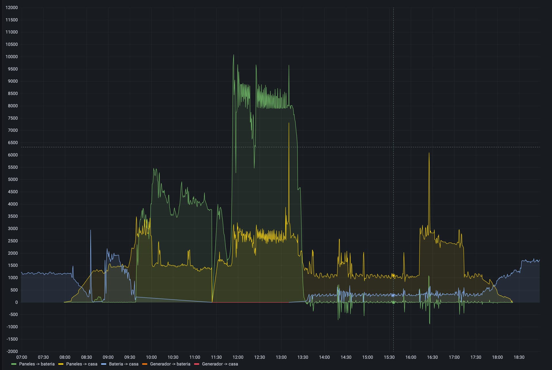
Below is a screen capture of a Grafana panel charting all 5 power flows over the last 12 hours; far from constant!
Enter the HA integration Integration - Riemann sum integral - Home Assistant
You’ll notice how spiky the power flows are so I use left method. The unit of prefix is k so we get kWh energy entities from the W power entities.
- platform: integration
  source: sensor.grid_to_house
  method: left
  unit_prefix: k
  name: Energy Grid to House
- platform: integration
  source: sensor.grid_to_battery
  method: left
  unit_prefix: k
  name: Energy Grid to Battery
- platform: integration
  source: sensor.generation_to_battery
  method: left
  unit_prefix: k
  name: Energy Generation to Battery
- platform: integration
  source: sensor.generation_to_house
  method: left
  unit_prefix: k
  name: Energy Generation to House
- platform: integration
  source: sensor.battery_to_house
  method: left
  unit_prefix: k
  name: Energy Battery to House
- platform: integration
  source: sensor.power_to_battery
  method: left
  unit_prefix: k
  name: Energy to Battery
Whereas the power flows go up and down, energy will always go up as it accumulates over time. Hence the following Grafana panel representing the energy spent/accumulated over the last 2 days (generator stays constant as it was not turned on during this period).

Remark: we’re in winter so as the number of sunny hours is less than the number of night hours the house gets most of its energy from the batteries, which are then charged during the day. In the power flows panel above you’ll notice the large peak of power from the solar panels to the batteries during the sun hours.
These energy accumulated graphs are interesting to look at long term trends but I’m interested in daily and monthly periods. Daily because that is our natural rhythm, and monthly because that is the invoicing frequency and even if I don’t pay invoices I’d like to know how much my investment is worth.
So we’ve started with the power flows in W which are instantaneous, integrated them over time to get energy in kWh, and now want to measure energy in daily and monthly buckets. Enter the HA Energy Dashboard and Utility Meters.
10. Energy Dashboard
HA Energy Dashboard is a convenient and good looking way to convert your power flows into daily energy balances, with the added bonus of cost calculation.

You’ll recognise the different energy entities we defined until now including the 2 Fronius PV inverters (it is night now, the solar inverters turn off on their own so those sensors are unavailable - all normal stuff).
HA Energy Dashboard accumulates these on a daily basis, weekly, monthly and yearly so we got our cycles covered right? Well, mostly…

The entities used by Energy Dashboard are internal to HA and as far as I know not available to be consumed directly, only through the dashboard. But we can easily create them using the Utility Meter integration Utility Meter - Home Assistant
We just need to configure as many entities as we want, each one for a cycle (hourly, daily, weekly, etc.) from the raw energy entities, and we get counters which reset every period. Here are some I have configured:
# utility meters
utility_meter:
  daily_energy_generation_to_battery:
    source: sensor.energy_generation_to_battery
    name: Daily Energy Generation to Battery
    cycle: daily
  daily_energy_generation_to_house:
    source: sensor.energy_generation_to_house
    name: Daily Energy Generation to House
    cycle: daily
  daily_energy_battery_to_house:
    source: sensor.energy_battery_to_house
    name: Daily Energy Battery to House
    cycle: daily
… and their graphical representation:

This doesn’t carry any more information than the Energy Dashboard, just different format and entities I can directly manipulate. Which I need to in order to get to the cost part of the picture.
… end of this post … to be followed