Victron VRM API
Victron VRM API Integration for Home Assistant
I’d like to present my first custom integration for the Victron VRM API. It’s perfect for mobile systems like motorhomes, caravans and boats where there is no local access to the Victron system. Of course, it can also be used in homes or other projects.
This integration use the Victron VRM Portal to get Data from the API. All you need for Setup are some Numbers from your VRM Portal.
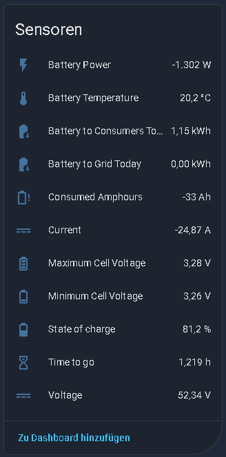
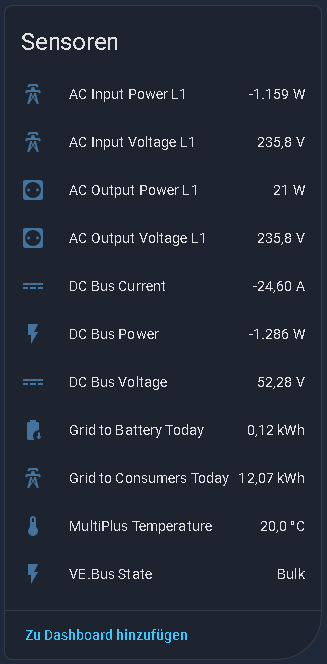
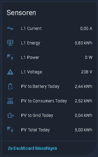
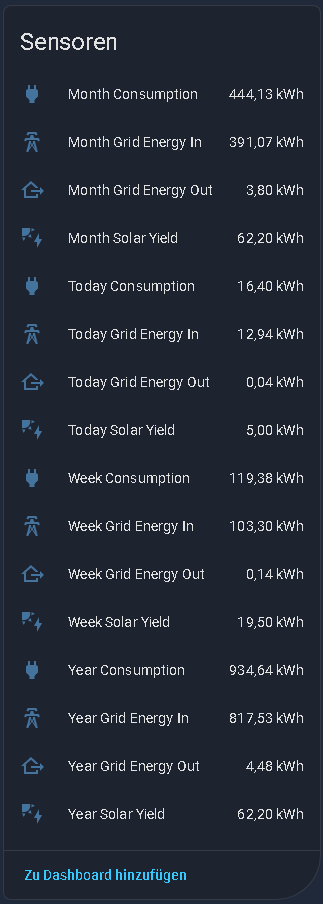
At this Time you can read the Data from Battery, MultiPlus, PV Inverter, Tank and Solar Charger. Also you get the Overall Stats for the Day, Week, Month and Year and a List of connected Devices. I’m working on it, to get some more Data from the victron API.
If you like the Integration, I would appreciate a Star rating ![]() from you.
from you. ![]()
VRM API supported Devices and Sensors
Overview Devices
| Device Type | Number of Sensors |
|---|---|
| Battery | 33 |
| MultiPlus | 11 |
| PV Inverter | 16 |
| Tank | 6 |
| Solar Charger | 7 |
| Overall Stats | 16 |
| Total | 89 |
Sensor Details
| Device Type | Sensor Name | VRM ID / Key | Unit | Description |
|---|---|---|---|---|
| Battery | State of charge | 51 |
% | State of Charge (SOC) |
| Battery | Voltage | 47 |
V | Battery Voltage |
| Battery | Current | 49 |
A | Battery Current |
| Battery | Consumed Amphours | 50 |
Ah | Consumed Amphours |
| Battery | Time to go | 52 |
h | Time to go until empty |
| Battery | Battery Temperature | 115 |
°C | Battery Temperature |
| Battery | Minimum Cell Voltage | 173 |
V | Minimum Cell Voltage (BMS) |
| Battery | Maximum Cell Voltage | 174 |
V | Maximum Cell Voltage (BMS) |
| Battery | Battery Power | (Calculated) | W | Current Power (V*A) |
| Battery | Battery Charge Cycles | 58 |
- | Full Charge Cycles |
| Battery | Battery to Consumers (Today) | Bc |
kWh | Energy to Load (Today) |
| Battery | Battery to Grid (Today) | Bg |
kWh | Energy to Grid (Today) |
| Battery | Low voltage alarm | 119 |
- | Low voltage alarm |
| Battery | High voltage alarm | 120 |
- | High voltage alarm |
| Battery | Low starter-voltage alarm | 121 |
- | Low starter-voltage alarm |
| Battery | High starter-voltage alarm | 122 |
- | High starter-voltage alarm |
| Battery | Low state-of-charge alarm | 123 |
- | Low state of charge |
| Battery | Low battery temperature alarm | 124 |
- | Battery temperature too low |
| Battery | High battery temperature alarm | 125 |
- | Battery temperature too high |
| Battery | Mid-voltage alarm | 126 |
- | Mid-voltage anomaly |
| Battery | Low fused-voltage alarm | 155 |
- | Low fused voltage |
| Battery | High fused-voltage alarm | 156 |
- | High fused voltage |
| Battery | Fuse blown alarm | 157 |
- | Fuse blown |
| Battery | High internal-temperature alarm | 158 |
- | Internal temperature alarm |
| Battery | Cell imbalance alarm | 286 |
- | Cell imbalance detected |
| Battery | High charge current alarm | 287 |
- | Charge current too high |
| Battery | High discharge current alarm | 288 |
- | Discharge current too high |
| Battery | Internal failure | 289 |
- | Internal failure detected |
| Battery | High charge temperature alarm | 459 |
- | Charge temperature too high |
| Battery | Low charge temperature alarm | 460 |
- | Charge temperature too low |
| Battery | Low cell voltage | 522 |
- | Low cell voltage |
| Battery | Charge blocked | 739 |
- | Charging blocked (BMS) |
| Battery | Discharge blocked | 740 |
- | Discharging blocked (BMS) |
| — | — | — | — | — |
| MultiPlus | AC Input Voltage L1 | 8 |
V | AC Input Voltage Phase 1 |
| MultiPlus | AC Input Power L1 | 17 |
W | AC Input Power Phase 1 |
| MultiPlus | AC Output Voltage L1 | 20 |
V | AC Output Voltage Phase 1 |
| MultiPlus | AC Output Power L1 | 29 |
W | AC Output Power Phase 1 |
| MultiPlus | DC Bus Voltage | 32 |
V | DC Bus Voltage |
| MultiPlus | DC Bus Current | 33 |
A | DC Bus Current |
| MultiPlus | VE.Bus State | 40 |
- | Operating State (e.g., Inverting) |
| MultiPlus | MultiPlus Temperature | 521 |
°C | Device Temperature |
| MultiPlus | DC Bus Power | (Calculated) | W | Current DC Power (V*A) |
| MultiPlus | Grid to Consumers (Today) | Gc |
kWh | Energy from Grid to Load (Today) |
| MultiPlus | Grid to Battery (Today) | Gb |
kWh | Energy from Grid to Battery (Today) |
| — | — | — | — | — |
| PV Inverter | L1 Voltage | 203 |
V | Voltage Phase 1 |
| PV Inverter | L1 Current | 204 |
A | Current Phase 1 |
| PV Inverter | L1 Power | 205 |
W | Power Phase 1 |
| PV Inverter | L1 Energy | 206 |
kWh | Energy Yield Phase 1 (Total) |
| PV Inverter | L2 Voltage | 207 |
V | Voltage Phase 2 |
| PV Inverter | L2 Current | 208 |
A | Current Phase 2 |
| PV Inverter | L2 Power | 209 |
W | Power Phase 2 |
| PV Inverter | L2 Energy | 210 |
kWh | Energy Yield Phase 2 (Total) |
| PV Inverter | L3 Voltage | 211 |
V | Voltage Phase 3 |
| PV Inverter | L3 Current | 212 |
A | Current Phase 3 |
| PV Inverter | L3 Power | 213 |
W | Power Phase 3 |
| PV Inverter | L3 Energy | 214 |
kWh | Energy Yield Phase 3 (Total) |
| PV Inverter | Status | 246 |
- | Status Code |
| PV Inverter | PV to Consumers (Today) | Pc |
kWh | Energy from PV to Load (Today) |
| PV Inverter | PV to Battery (Today) | Pb |
kWh | Energy from PV to Battery (Today) |
| PV Inverter | PV to Grid (Today) | Pg |
kWh | Energy from PV to Grid (Today) |
| PV Inverter | PV Total Today | (Calculated) | kWh | Total PV Yield Today (Pc+Pb+Pg) |
| — | — | — | — | — |
| Tank | Capacity | 328 |
m³ | Tank Capacity |
| Tank | Type | 329 |
- | Fluid Type |
| Tank | Level | 330 |
% | Fluid Level in Percent |
| Tank | Remaining | 331 |
m³ | Remaining Fluid Volume |
| Tank | Status | 443 |
- | Tank Status (e.g., OK) |
| Tank | Custom Name | 638 |
- | User Defined Name |
| — | — | — | — | — |
| Solar Charger | Battery Watts | 107 |
W | Charging Power to Battery |
| Solar Charger | Battery Voltage | 81 |
V | Battery Voltage |
| Solar Charger | Charge State | 85 |
- | Charger State (e.g., Bulk, Float) |
| Solar Charger | Battery Temperature | 83 |
°C | Battery Temperature (external) |
| Solar Charger | Yield Today | 94 |
kWh | Energy Yield Today |
| Solar Charger | Yield Yesterday | 96 |
kWh | Energy Yield Yesterday |
| Solar Charger | Relay Status | 90 |
- | Relay State |
| — | — | — | — | — |
| Overall Stats | * Total Solar Yield | total_solar_yield |
kWh | Total PV Yield (for selected period) |
| Overall Stats | * Total Consumption | total_consumption |
kWh | Total Consumption (for selected period) |
| Overall Stats | * Grid Energy In | grid_history_from |
kWh | Energy from Grid (for selected period) |
| Overall Stats | * Grid Energy Out | grid_history_to |
kWh | Energy to Grid (for selected period) |
(The Overall Stats Entities are build for Periods Today, Week, Month and Year.)
 Prerequisites
-
VRM access token (keep this secret!). Create one in the VRM Portal under Preferences > Integrations > Access tokens or use this link.
-
your SiteID (VRM-Installations-ID)
-
Instance Number from Battery, Multiplus and PV Inverter

 Installing the Integration
 HACS
HACS
- Simply follow the Link to integrate this repository to HACS
![]()
- go to
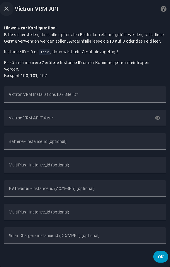
Settings -> Devices and Services -> Integration - click on
Add Integration - search for
victron vrm apior shortvrm - fill in your Side_ID, Token and Instance_ID for Battery, Multiplus and PV Inverter
Manual
- dowonload the latetest Release
- copy the folder “victron-vrm-api” inside your custom_components of Home Assistant
- restart home assistant
- go to
Settings -> Devices and Services -> Integration - click on
Add Integration - search for
victron vrm apior shortvrm - fill in your Side_ID, Token and Instance_ID for Battery, Multiplus and PV Inverter
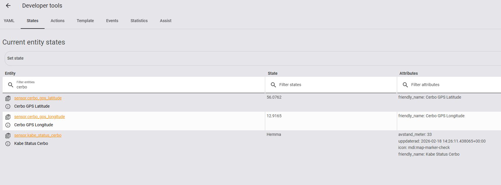
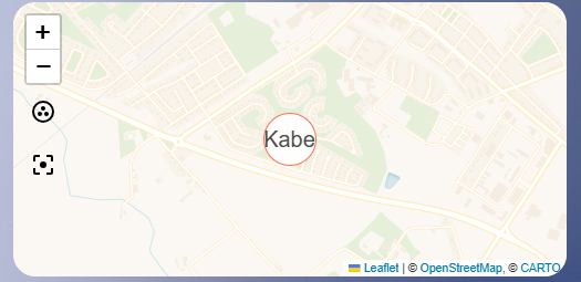
 How it looks in HA
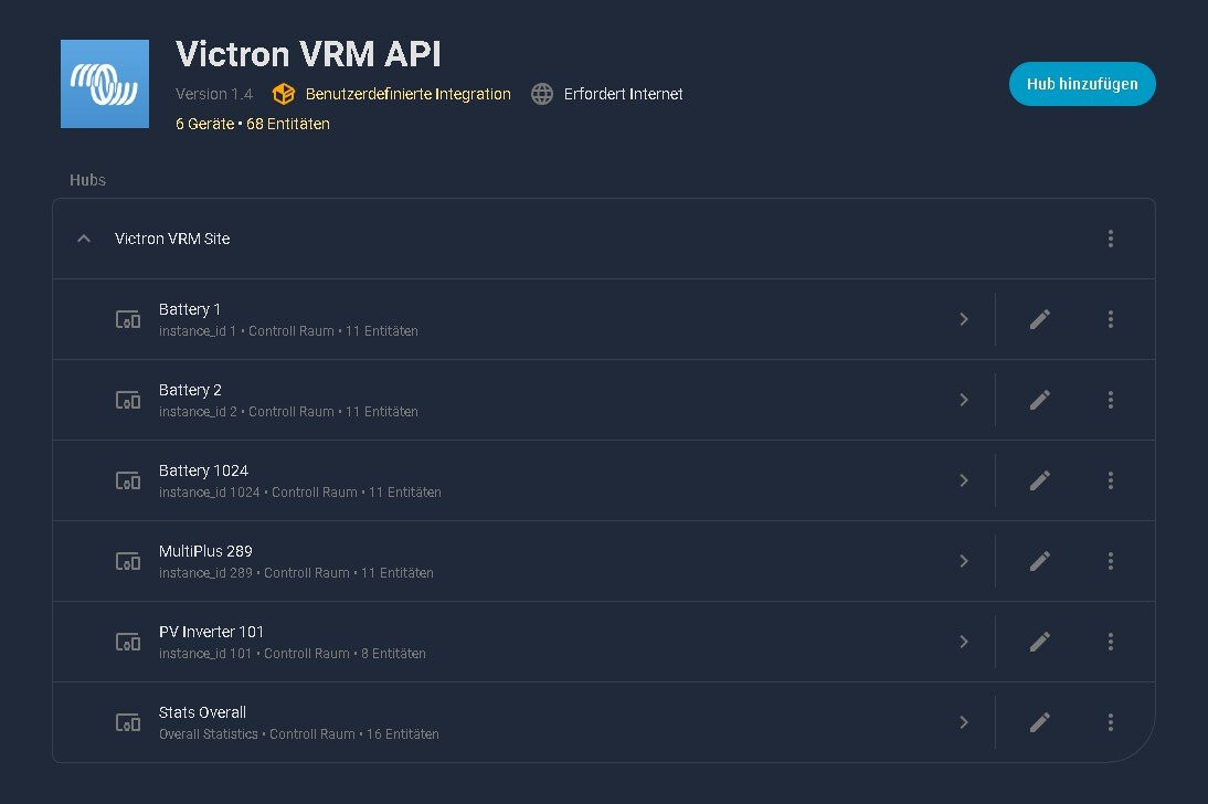
Q&A
- Configuration Menu, if the instance number for Battery, Multiplus or PV Inverter is set to 0 or is blank, then no device will be added!
(Example, if you have no Battery, then you don`t need the empty Device in HA.) - You get the Temperature value with a 1PH Multiplus Setup. With 3Ph Multiplus Setup you dont get this Sensor.
- You can add more instance ids separated by comma (100, 101, 102)
- You get Data from your 1Ph or 3Ph PV-Inverter. With 3Ph you get some more Sensors.